2
Description of Relay
7UT51 v3
26 PRIM-2330C
2.12 Thermal Overload Protection (49
-
1 and 49
-
2)
Table 2.9
Specifications for Thermal Overload Protection (49
-
1 and 49
-
2)
Settings
Operational status Active, inactive, or block
-
contacts; choice can be temporarily
changed using binary
-
signal inputs
Maximum Continuous Overload Current k factor (Imax/In) 0.10 to 4.00 (0.01 steps)
Time Constant 1.0 to 999.9 min (0.1 min. steps)
Thermal Warning Stage 50 to 100% referred to trip temperature rise
Current Warning Stage 0.10 to 4.00 times In (0.01 steps)
Events that can control signal contacts, trip contacts, or
LEDs
Change in operational status; pickup, dropout, trip, and reset
events, start of time delay before trip. All events are logged, as
are the amplitude of the ground current and the phase
-
angle
difference at the time of a trip.
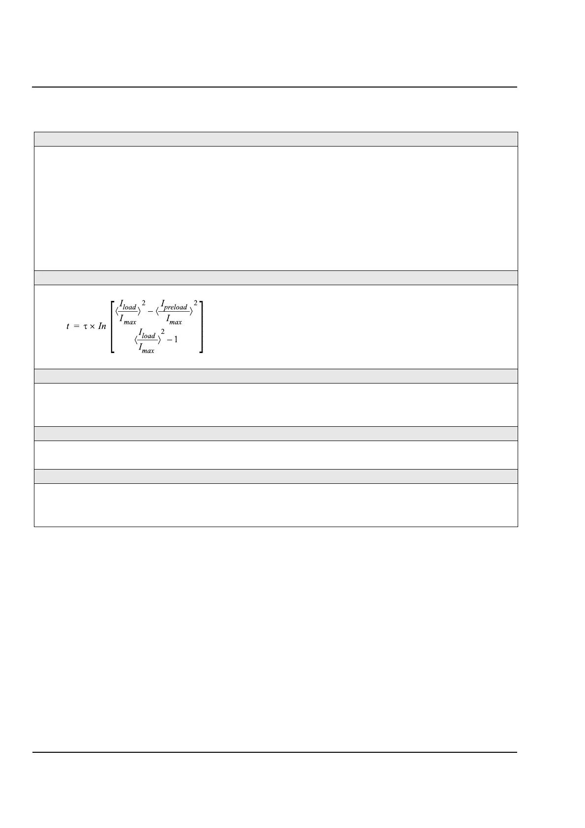
Trip Time Characteristic
τ is a constant describing the thermal behavior of the
object (see Section 9.3.2 on page 108).
I
load
is the present measured load current.
I
preload
is the previous measured load current.
I
max
is the maximum allowed continuous overload current
(a setting, see Section 9.3.1 on page 108)
ln means “the natural logarithm of…”
Dropout Ratios
(approx.) 0.99
(approx.) 0.99
I/I
warn (approx.)
0.99
Operating Tolerances (with default settings)
k times In ±10% of characteristic value (for k×
I
n
)
Trip time ±10% of setting value or 2s, whichever is greater
Effect of Environmental Influences on Times and Tolerances
Supply power voltage ≤ 1% if between 80% and 115% of nominal voltage
Ambient temperature ≤ 0.5% / 10 K if between
-
5°C and 40°C (23°F and 104°F)
System frequency ≤ 1% if between 95% and 105% of nominal frequency
τ
Θwarn()Θtrip()⁄
ΘΘtrip()⁄
ΘΘwarn()⁄
 Loading...


