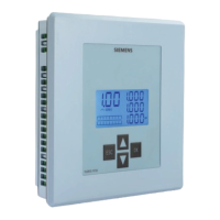
7UT51 v3
Transformer Differential Protection (87T and 87HS)
4
PRIM-2330C 55
As for the ground-current inputs, the relay must know
the rated nominal primary current and orientation of
the CT(s) measuring ground or neutral currents. The
addresses corresponding to each winding are used
only if a CT is connected to relay’s ground current
inputs and assigned in addresses 7806 and 7807.
4.4 Trip Characteristic
As shown in Figure 4.9, current transformers (CTs)
measure the currents flowing into and out of the
protected transformer. As described in Section 4.1.1
on page 39, the relay matches the currents to take into
account the winding ratio(s) of the protected
transformer, the winding ratios of the CTs, the phase
shift(s) of the protected transformer, and the
processing of the zero sequence current. The
differential protection function then calculates
(separately for each phase) the “differential current,”
I
diff
:
(two winding transformer) (4.7)
(three winding transformer)(4.8)
The differential current,
I
diff
, is a scalar quantity that is
the absolute value of the amplitude of the vector sum
of the fundamental component of each matched
phase-current flowing into the protected transformer.
In a system composed of ideal components, a
non-zero differential current is a certain indication of a
fault somewhere within the protected transformer.
As described in Section 4.1.2 on page 41, the
non-ideal behavior of a real system may result in a
differential current when in fact no fault exists within
the protected transformer. In these cases, the
differential protection must be restrained. To do so, the
relay calculates (separately for each phase) a
“restraining current,”
I
rest
:
(two winding transformer)
(4.9)
(three winding transformer)
(4.10)
The restraining current,
I
rest
, is the scalar sum of the
absolute value of the amplitude of the fundamental
component of each matched phase-current flowing
into the protected transformer. It is proportional to the
total amount of current flowing through the
transformer.
Note:
By definition both
I
diff
and
I
rest
are positive
values, and that
I
rest
is always greater than or
equal to
I
diff
.
To illustrate the use of the restraining current, consider
three operating situations for a two-winding
transformer:
• During normal operation, or through fault (outside
of the protected transformer), , so:
(4.11)
(4.12)
• If there is a short circuit within the protected
transformer with equal currents entering from
each side, , so:
(4.13)
(4.14)
1107 In CT STP1 (7UT513 only)
1127 In CT STP2 (7UT513 only)
1147 In CT STP3 (7UT513 only)
Rated nominal primary current of each winding’s
ground
-
current or neutral
-
current CT (if the winding has
one).
Range: 1
–
100,000 A
Default: 200 A for Winding 1, 2000 A for windings 2 and 3
1108 CT1 GND
-
PT (7UT513 only)
1128 CT2 GND
-
PT (7UT513 only)
1148 CT3 GND
-
PT (7UT513 only)
Orientation of which end of each winding’s ground
-
CT is
connected to the non
-
polarity terminal of a ground
-
current
input of the relay. This is usually the non
-
polarity end of the
CT (see Figure 4.5 and Figure 4.4).
Option Description
TOWARDS TRANSF Towards the transformer (default).
TWDS LINE/BUSBAR Away from the transformer.
I
diff
=
′
+
′
II
12
I
diff
=
′
+
′
+
′
II I
12 3
I
rest
=
′
+
′
II
12
I
rest
=
′
+
′
+
′
II I
12 3
′
=−
′
II
21
I
diff
=
′
+
′
=
′
−
′
=
II II
12 11
0
I
rest
=
′
+
′
=
′
+−
′
=⋅
′
II I I I
12 1 1 1
2
′
=
′
II
21
I
diff
=
′
+
′
=
′
+
′
=⋅
′
II II I
12 11 1
2
I
rest
=
′
+
′
=
′
+
′
=⋅
′
II II I
12 11 1
2

 Loading...


