13
Binary-Signal Inputs, Signal Contacts, Trip Contacts, and LED Indicators
7UT51 v3
126 PRIM-2330C
13.2 Binary
-
Signal Inputs
Binary-signal inputs (also called discrete inputs, input
contacts, or binary inputs) enable the relay to respond
to signals communicated by applying (or removing) a
voltage across a pair of signal-input terminals. A
7UT512 relay has two binary-signal inputs, while a
7UT513 has five. Each binary signal input contact can
control up to ten events, with each event
independently configured to be active when voltage is
applied to the terminals (HI) or when voltage is
removed from the terminals (LO).
The input functions will have no effect if the
corresponding protection function is not ENABLED in
the relay or has been set to OFF.
Binary input can also perform the following functions:
• Change the settings set (see Section 14.4.2 on
page 143)
• Synchronize the internal clock (Event 3)
• Reset the front panel LEDs (Event 5)
• Trigger a waveform capture (see Section 14.7 on
page 147)
6101 BINARY INPUT 1 [default is 5 >Reset LEDs HI]
6102 BINARY INPUT 2 [default is 2306 >BU50HS BLK HI]
6103 BINARY INPUT 3 (7UT513 only) [default is 11 >UsrDefEvent1 HI]
6104 BINARY INPUT 4 (7UT513 only) [default is 391 >Buchh. Warn HI]
6105 BINARY INPUT 5 (7UT513 only) [default is 392 >Buchh. Trip HI]
Each discrete input can be associated with up to ten (10) functions that will be activated when the corresponding discrete
input is active. Each function can be independently configured to be active when the input is active (HI) or active when the
signal is inactive (LO).
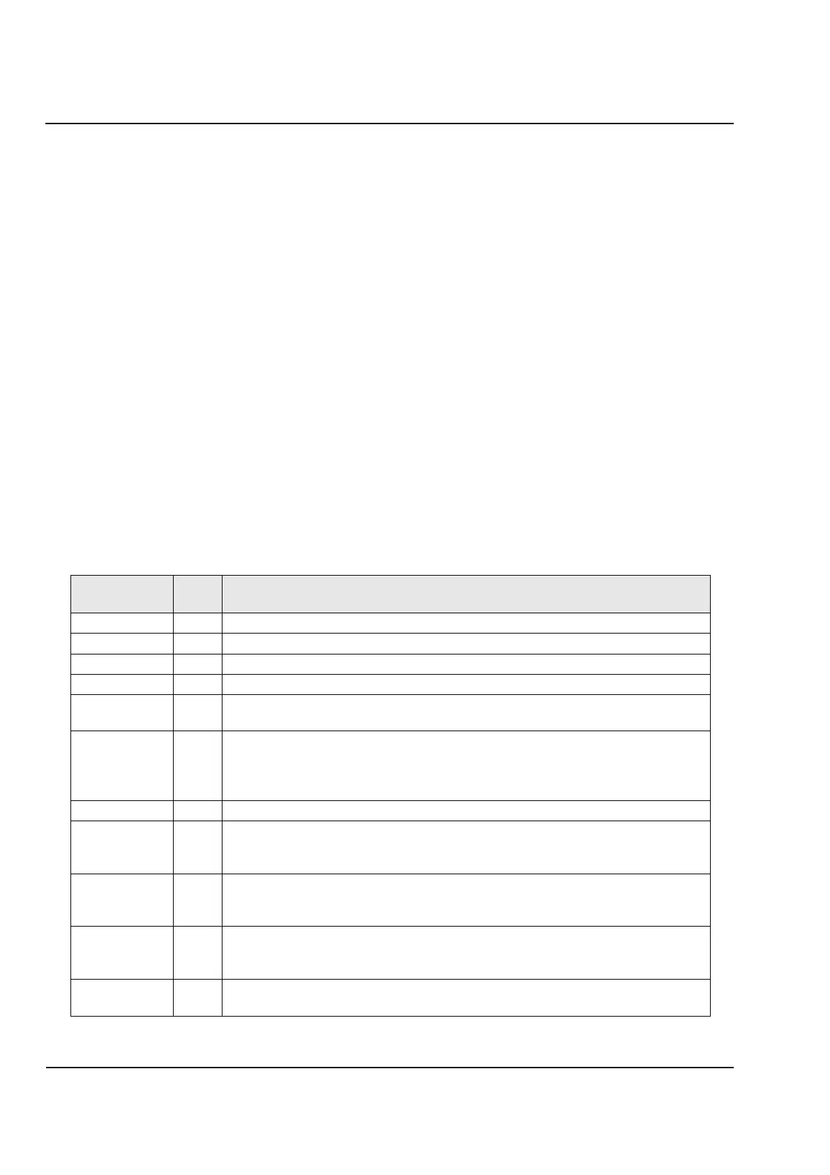
LCD
Abbreviation
Event Effect of Input Signal
not allocated 1 If the input is associated with less than ten functions, the unused slots are “not allocated”.
>Time Synch 3 Synchronize internal real time clock when input signal goes HI (or LO).
>Trig. wave 4 Start waveform recording when input signal goes HI (or LO).
>Reset LEDs 5 Reset front panel LED indicators when input signal goes HI (or LO).
>ParamSelect.1
>ParamSelect.2
7
8
Change the
active parameter set
(must be used with a pair of binary inputs, see
Table 14.1) when input becomes active.
>UsrDefEvent1
>UsrDefEvent2
>UsrDefEvent3
>UsrDefEvent4
11
12
13
14
The four user defined events have no effect on relay operation, but can be mapped to
LEDs (to display) and signal relay outputs (to pass along to another device).
>Manual Close 356 Circuit breaker has been manually closed (signal from discrepancy switch)
>Buchh. Warn
>Buchh. Trip
>Buchh. Tank
391
392
393
No effect on relay operation. Status of
Buchholz
protection (warning, trip, or tank pickup)
can be mapped to LED and signal relay outputs.
>49 O/L1 BLK
>49 O/L1 EVNT
>49 O/L1 BLK
1553
1554
1555
If thermal overload protection
49
-
1
is enabled, it will be blocked (1553), will only generate
alarms (1554), or will be blocked from issuing a trip command (1555) as long as the
signal input is active
>49 O/L2 BLK
>49 O/L2 EVNT
>49 O/L2 BLK
1603
1604
1605
If thermal overload protection
49
-
2
is enabled, it will be blocked (1603), will only generate
alarms (1604), or will be blocked from issuing a trip command (1605) as long as the
signal input is active.
>BU BLOCK
>BU BLK Trip
2303
2304
Backup overcurrent protection will be blocked (2303) or will be blocked from issuing a trip
command (2304).
 Loading...


