7UT51 v3
Binary-Signal Inputs, Signal Contacts, Trip Contacts, and LED Indicators
13
PRIM-2330C 125
Figure 13.4
Trip Contacts
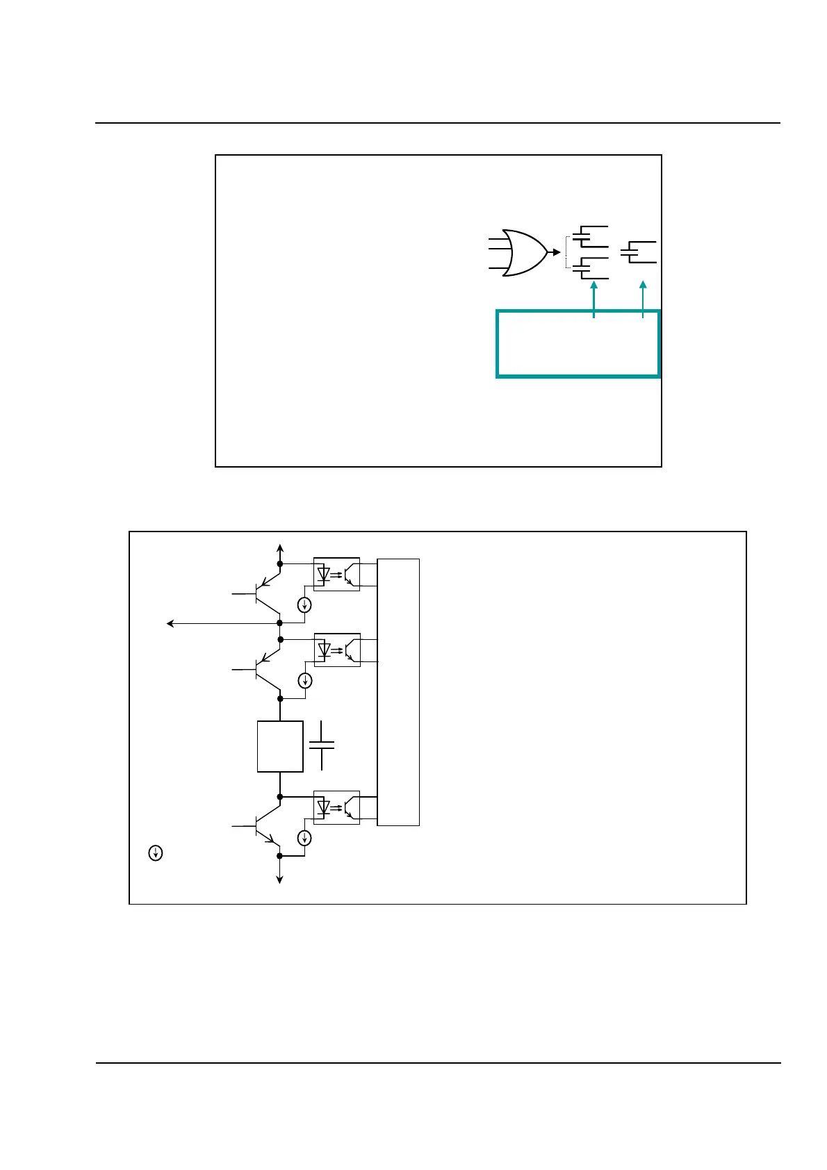
Figure 13.5
Trip Contact Monitoring Circuit
Each signal contact is controlled
by up to 20 events.
For example:
0511 General Trip of the Relay
1571 49-1 Thermal Overload Trip
1621 49-2 Thermal Overload Trip
2451 Backup Overcurrent Trip
4537 External Event 1 Trip
5673 87 Diff Trip Phase B
5691 87 Diff Trip
5821 87N RGF Trip
5921 64T Tank Trip
Use to...
Trip circuit breakers
Trip Contacts
7UT512: 2 0
7UT513: 3 2
Make Capacity: 1000 W/VA
Break Capacity: 30 W/VA
Switching Voltage: 250 V
Permissible Current: 5 A continuous
30 A for 0.5 s
Event 1
Event 2
:
:
Event 20
Trip
Contact
Trip Relay
Coil
TR
T1
T2
TCML
To second Trip Contact
TCML:
Trip Circuit Monitoring Logic
Constant current source
with Field effect Transistors
• One Trip Contact is controlled by two
Transistors (T1 & T2)
• For a pair of Trip Contacts, there is an
additional Release Transistor (TR)
• During normal operation, a trip contact is
inactive. If all Transistors are healthy (high
resistance), a low current will flow over the
opto-coupler Diodes and the Trip-contact-coil.
• If a Transistor is switched on, the opto-coupler
will be inactive.
• Sequentially, each Transistor can be switched
on and off, to test the status of the transistor
and the opto-coupler
• In case of Trip-command, all Transistors are
switched on.
• The status of the Trip Transistors and the trip
coil is monitored continuously.
 Loading...


