13
Binary-Signal Inputs, Signal Contacts, Trip Contacts, and LED Indicators
7UT51 v3
124 PRIM-2330C
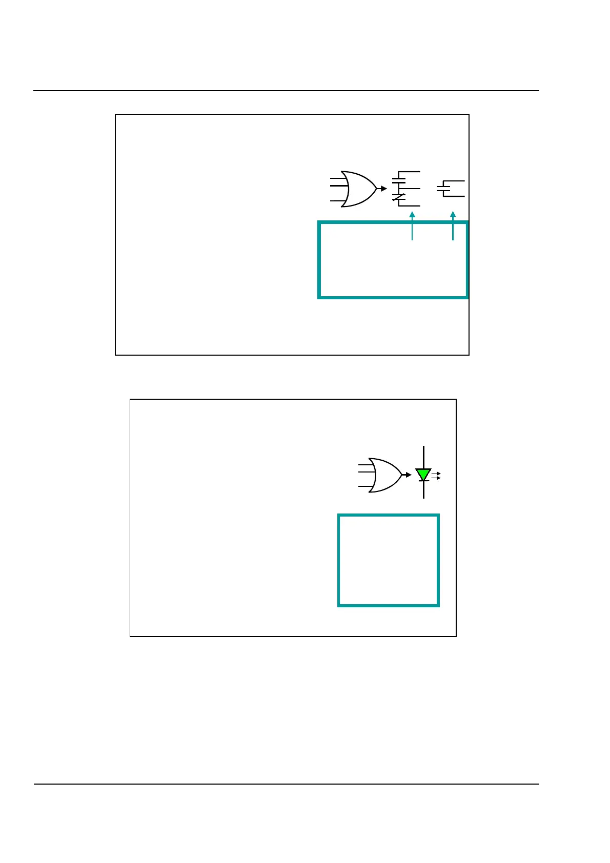
Figure 13.2
Signal Contacts
Figure 13.3
LED Targets
Each signal contact is controlled
by up to 20 events.
For example:
0141 Failure of internal 24V power supply
0511 General trip of the relay
1566 49-Thermal O/L prot.1: Thermal warn.
1571 49-Trip by thermal O/L protection 1
5671 87-Diff protection: General Trip
5821 Restricted Ground Fault: General Trip
5921 Transformer tank prot: General trip
Use to...
Sound alarms for operators
Signal other protection devices
Signal Contacts
Event 1
Event 2
:
:
Event 20
Make Capacity: 20 W/VA
Break Capacity: 20 W/VA
Switching Voltage: 250 V
Permissible Current: 1 A
Configurable
7UT512: 4 0
7UT513: 5 5
Self-Test Alarm: 1
Each LED is controlled by up to 20 events.
For example:
95 Parameters are Being Set
163 Failure: Current Symmetry Supervision
501 General Fault Detection
1566 Thermal Overload 1 Warning Stage
1571 Trip by Thermal Overload Protection 1
4533 External Trip 1 is Active
5616 87 Function is Blocked
5621 87 Time Delay Started
5641 87 Function Blocked by Harmonics
5651 87 Blocked by Saturation on Phase A
5817 87N Time Delay Started
Each event can either latch (“memorized”),
or not latch (“not memorized”) an LED.
Latched LEDs can be reset using a key on
the front panel, a binary-signal input, or an
attached PC running WinDIGSI.
LED Targets
Event 1
Event 2
:
:
Event 20
Power: 1
Blocked: 1
Configurable
7UT512: 6
7UT513: 14
 Loading...


