7UT51 v3
Ground Differential Protection (87N)
7
PRIM-2330C 93
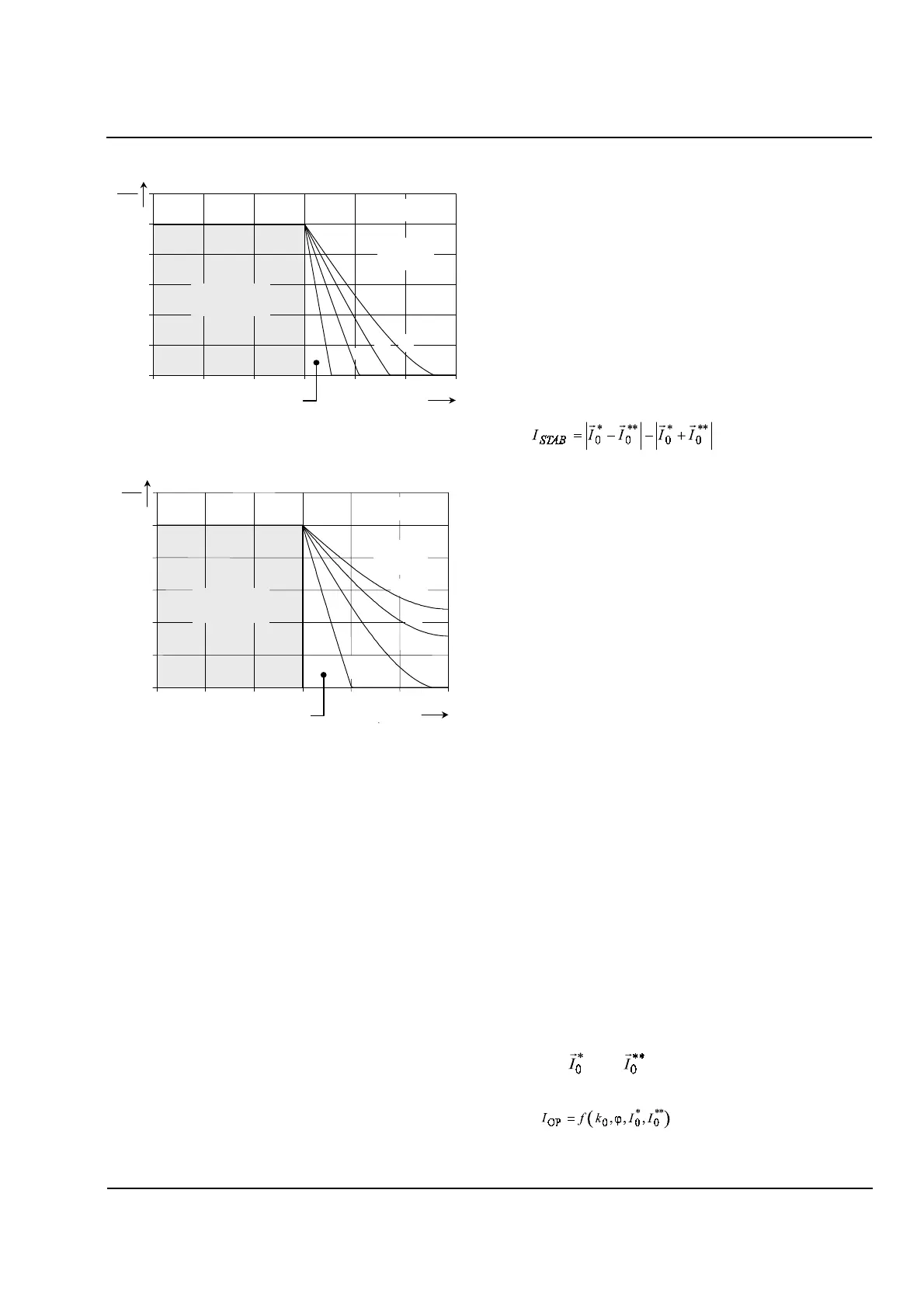
Figure 7.5
Trip Area for I*o/Io** = 2
Figure 7.6
Trip Area for I*o/Io**=4
Fault Detection
The algorithm detects that a fault has occurred if the
differential current,
I
D
, exceeds a relay setting
(indicating that the ground current and zero sequence
current differ too much), or if the restraining current,
I
R
,
exceeds another relay setting (indicating that the total
amount of current flowing through the transformer is
too high). Once a fault has been detected, further
analysis occurs. As with the classical solution, the
question to be answered is whether the fault is internal
(requiring a trip) or external (not requiring a trip).
7.2 Trip Decision
In theory, an external fault can be easily recognized
since the calculated quantities I
0
* and I
0
** will have
equal magnitudes and a phase angle difference of ϕ =
90°. In reality, inrush effects or CT-saturation may
distort the measured currents. CT-saturation can
affect both the perceived amplitudes of the
fundamental current vectors and the phase angle
between them.
Classical Trip Area:
The algorithm calculates a value called
the “stabilization current,”
I
STAB
:
(7.9)
Vector analysis can show that the amplitude of the
stabilization current,
I
STAB
, will be negative if the phase
angle
ϕ
between I
0
* and I
0
** is in the range −90° ≤ ϕ ≤
90°. In this case, the fault is internal, so a trip is
appropriate if the amplitude of a calculated “operating
current,”
I
OP
, is above a minimum level (a relay
setting):
(if −90° ≤ ϕ ≤ 90°) (7.10)
Trip if (if −90° ≤ ϕ ≤ 90°)(7.11)
Extended Trip Area:
The algorithm
extends the trip
area
to recognize internal faults that the classical
solution will fail to respond to, while still avoiding an
improper trip if the fault is external.
If the phase angle ϕ is in the range 90° ≤ ϕ ≤ 270°
(outside the classical trip area), the magnitude of
I
STAB
will be positive. In this case, the algorithm still bases
the trip decision on the amplitude of the operating
current,
I
OP
, but calculates
I
OP
differently:
(if 90° ≤ ϕ ≤ 270°) (7.12)
Trip if (if 90° ≤ ϕ ≤ 270°) (7.13)
where
k
0
, the “stabilization factor,” is a relay setting
used to adjust the sensitivity of the protection when
90° ≤ ϕ ≤ 270°. Note that when ϕ is in that range,
I
OP
is
a function of
four
quantities: the amplitudes of the
currents and , the phase angle between them,
and the stabilization factor,
k
0
:
0.0
0.2
0.4
0.6
0.8
1.0
1.2
0 30 60 90 120 150 180
2/
**
0
*
0
=
II
4.06
2.04
*
0
I
I
OP
ϕ
(degrees)
k
0
= 1.03
1.37
EXTENDED TRIP AREA
CLASSICAL
TRIP AREA
BLOCK
AREA
0.0
0.2
0.4
0.6
0.8
1.0
1.2
0 30 60 90 120 150 180
2.0
4
1.37
4/
**
0
*
0
=
II
*
0
I
I
OP
ϕ
(degrees
k
0
= 1.03
4.0
6
CLASSICAL
TRIP AREA
EXTENDED TRIP AREA
BLOCK
AREA
*
0
II
OP
=
SETTripOP
II
_
≥
STABOP
IkII
0
*
0
−=
 Loading...


