7UT51 v3
Motor or Generator Differential Protection (87M/G)
5
PRIM-2330C 69
5.3 Describing the CT
Scheme
Unlike electromechanical relays, numerical relays do
not require a complicated current transformer scheme
to match measured currents. Instead, information
about the protected object and the current
transformers is entered into the relay’s memory. Then,
using the measured currents, the relay performs any
necessary calculations to match the currents. The
relay must be configured with the information about
the CTs attached to the motor/generator and how they
are connected, including:
• The orientation of the current transformers
• The nominal
primary
rating of the current
transformers
• The nominal
secondary
rating of the current
transformers
• The manner in which the ground-current inputs
are used (7UT513 only)
This section describes the associated settings.
5.3.1 CT Orientation
In normal operation, the current has the same
magnitude and phase on both sides of the motor or
generator. Hence, the only information required is the
orientation of the CTs (relative to each other) and the
rated nominal primary current of each CT set.
If both CT commons are toward or away from the
motor or generator, the CT orientation is
SAME SIDE
(as in Figure 5.1 on page 70); otherwise the CT
orientation is
OPPOSITE SIDES
; however, when
using the relay for transverse differential protection,
the CT commons must be on the same side, but
specify
OPPOSITE SIDES
.
1203 VA M/G
Rated apparent power of the motor or
generator
Range: 0.2
–
5000.0 MVA
Default: 400.0
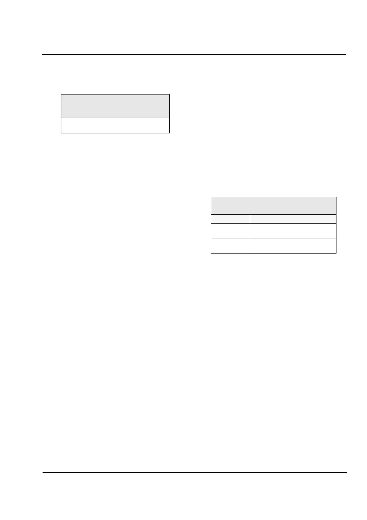
1206 CT STARPT
Orientation of CTs
Option Description
SAME SIDE Both CT commons on same side
of motor or generator (default)
OPPOSITE
SIDES
CT commons on opposite sides of
motor or generator
 Loading...


