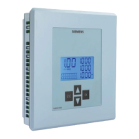
7UT51 v3
Protection Self-Monitoring
12
PRIM-2330C 121
The relay detects non-symmetric currents if the ratio of
the magnitude of I
min
to the magnitude of I
max
is
smaller than a setting value, “SYM. Fact. I” (setting
2904):
(12.1)
When all the phase currents are small, they may be
non-symmetrical for reasons other than a faulty CT
circuit. Hence, no action is taken unless the value of
I
max
is greater than a sensitivity threshold value,
“SYM.Ithres” (setting 2903):
(12.2)
If the ratio of I
min
to I
max
is in the BLOCK area of
Figure 12.1, the relay will report that the currents are
non-symmetric for that particular winding (or bus
branch).
Figure 12.1
Current Symmetry Monitoring
12.4.2 Current Summation
If the relay is protecting a bus, an additional protection
self-monitoring feature is available. If the differential
current of any phase has a magnitude corresponding
to a load current, the relay assumes that a CT circuit is
faulty and blocks the differential protection. The details
and settings for this feature are described in
Section 6.6 on page 86.
2903 SYM.Ithres
Current threshold above which at least one phase current
of the winding (or bus branch) must be before
current
-
symmetry monitoring will react (see Figure 12.1).
Range: 0.10
–
1.00
In
Default: 0.50
2904 SYM.Fact.I
Ratio of minimum measured current to maximum
measured current below which current symmetry
monitoring will react (see Figure 12.1).
Range: 0.00
–
0.95
Default: 0.50
I
I
min
max
< SYM.Fact.I
I
max
> SYM. Ithres
Magnitude of ma imum phase urrent,
( as a fra tion of )
I
I
n
00 05
10
Magnitude of minimum phase urrent,
( as a fra tion of )
I
I
n
00
05
10
Slope = S M Fa t (setting 2904)
OC Area
S M thres
(setting 2903)

 Loading...


