7UT51 v3
Bench Testing
16
PRIM-2330C 161
For testing the differential protection, this function
must have been configured as Exist (Address 7816)
and the protected object (Address 7801) must be a
2WIND-TRANSF or a 3WIND-TRANSF (7UT513 only)
or a 1PHASE-TRANSF. Additionally, it must be
parameterized as operative, On in Address 1601.
Since differential protection is sensitive to
single-ended currents, one can simultaneously test
that the relay does not trip for through current. If
backup overcurrent protection is used in the relay,
ensure that the through current applied does not
exceed the pickup of the overcurrent function.
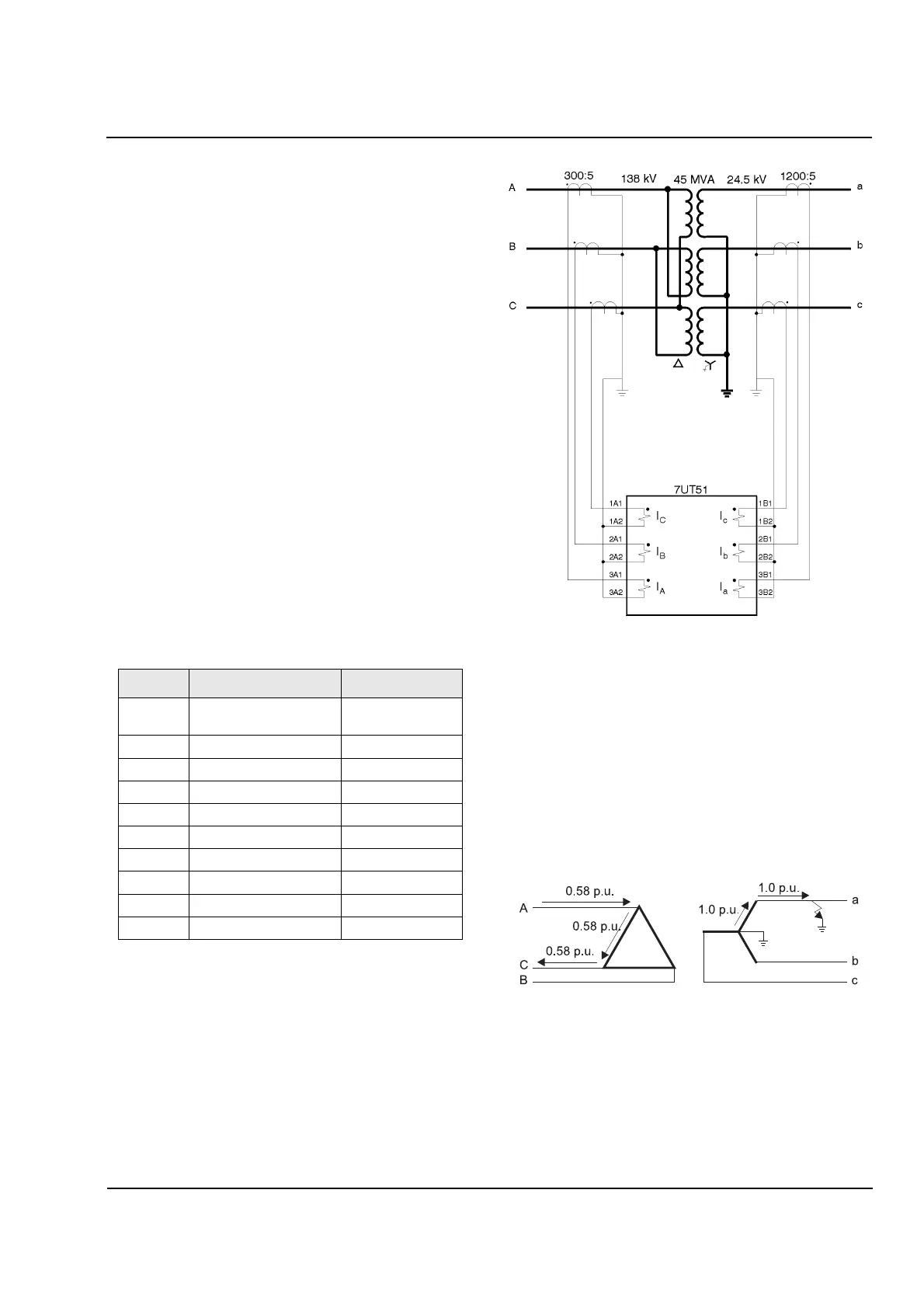
The following test procedure is written for a standard
delta-wye transformer connected as shown in
Figure 16.1. Settings for this example are shown in
Table 16.2. If your application varies, determine how
current typically flows for the simplest fault in your
system and trace the currents through the CTs to the
relay inputs (similarly to the method shown in this
example). For instance, if the transformer is a
wye-wye or delta-delta with no phase shift, the
differential relay can be tested by applying only one
phase current to each “side” of the relay (the correct
polarity and magnitudes must also be considered) that
is, to phase A primary and phase a secondary.
Table 16.2
Example Settings
Figure 16.1
Sample Three
-
Phase Connection Diagram
When performing testing other than three-phase
testing for the 7UT51 relay and protecting a
transformer with a 30 degrees phase shift, keep in
mind the underlying physical principles. For instance,
if a single-phase to ground-fault on phase ‘a’ occurs
on the wye side of an ANSI connected transformer,
current will flow as shown in Figure 16.2. The relay
would see current in phases A and C (180 degrees
apart) on the delta side of the transformer. This is
typical for any delta connection.
Figure 16.2
Single
-
Phase Fault on Wye Side of
Delta
-
Wye Transformer
Address Description Value
1103,
1123
Trans. Winding
1&2,kVA
45,000
1102 kV
L
-
L
,
W1
138
1122 kV
L
-
L
,
W2
24.5
1142 kV
L
-
L
,
W3
24.5
1121 Vector Group d1
1141 Vector Group d1
1104 In CT Winding 1, amps 300 (CT 300/5)
1124 In CT Winding 2, amps 1200 (CT 1200/5)
1144 In CT Winding 3, amps 1200 (CT 1200/5)
1147 In CT STP3, amps 600 (CT 600/5)
Note:
All other parameters remain at default settings
unless otherwise noted in individual test
instructions. Some addresses may not be
available until its protective function is enabled.
 Loading...


