18
Field Testing and Commissioning
7UT51 v3
200 PRIM-2330C
The polarities of the through flowing currents are
defined to be equal. When currents of equal phase
flow through the protected object, the angle difference
is 0
o
, provided the connections are correct. The
theoretical angle value depends on the protected
object, the transformers, and the connection group
entered into the relay (see Table 4.1 and Table 4.2).
The measured angles must be equal for all three
phases. If not, individual phases are interchanged.
The polarity of the current connections and the
parameterized polarity are taken into consideration
when the angles are displayed. Thus, if all three
angles differ by 180
o
from the theoretical value, the
polarity of one complete current transformer set is
wrong. This can be corrected by checking and
changing the corresponding plant parameters:
• Address 1105 for the primary winding of a
transformer
• Address 1125 for the secondary winding of a
transformer
• Address 1206 for generators or motors
• Address 1303 for Side 1 of a branch point
• Address 1305 for Side 2 of a branch point
Note:
The connection group of power transformers is
defined from the higher voltage side to the
lower voltage side. The angle (vector group *
30°) is valid only when measurement is carried
out in this way. That is, the test source is on the
higher voltage side and the short-circuit
bridges are on the lower voltage side. If
measurement is carried out from the lower
voltage side, the angle must be: 360° - vector
group*30°.
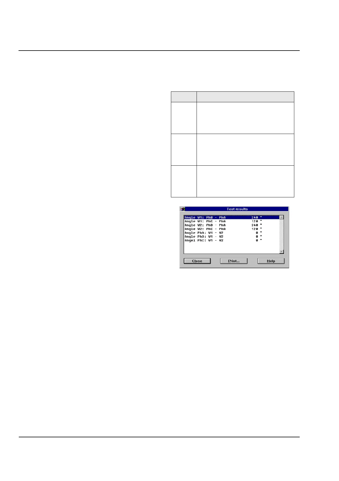
Figure 18.4
WinDIGSI Screen example of the angle
measurement of the line currents.
Before the tests with symmetrical currents are
terminated, the differential and stabilizing currents are
checked. Even though the previous tests should have
detected all connection errors, nevertheless, errors
are possible concerning current matching and the
assignment of the connection group. Page to
Address 4161. In this Address, the calculated values
can be read out by scrolling through the display with
the
No
key or
Backspace
key. Note that the
differential and stabilizing values are referred to the
rated current of the protected object.
Address Test Message
4121
Test Angle L
I1L1
-
I2L1=0
o
-
display of phase angle
between the currents of Side 1, phase L1
against Side 2, phase L1, refer to
Table 4.1 and Table 4.2
4121
Test Angle L
I1L2
-
I2L2=0
o
-
display of phase angle
between the currents of Side 1, phase L2
against Side 2, phase L2, should be 120
o
refer to Table 4.1 and Table 4.2
4121
Test Angle L
I1L3
-
I2L3=0
o
-
display of phase angle
between the currents of Side 1, phase L3
against Side 2, phase L3, should be 120
o
refer to Table 4.1 and Table 4.2
 Loading...


