16
Bench Testing
7UT51 v3
170 PRIM-2330C
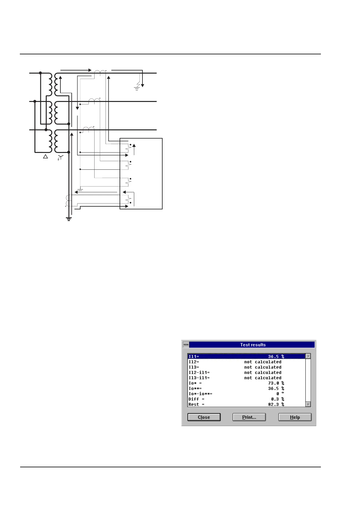
Figure 16.12
Current Flow for Restricted Ground Fault
Outside of Protected Zone
The sum of the currents for an ‘external’ ground-fault
(as shown in Figure 16.12) add to 0, indicating no
ground-fault in the RGF zone.
External Fault Test
Using the test configuration as shown in Figure 16.10,
apply currents as follows to emulate the condition
shown in Figure 16.12, Restricted Ground Fault
Outside of Protected Zone. Note the polarity of I
2
.:
I
1
= 1.81A
I
2
= I
1
x CT
W2
/ CT
STP3
= 1.81A x 1200 / 600
= 3.62A
The relay should not trip.
To view the values of the RGF test results, use either
the front display of the relay or WinDIGSI software on
a PC.
To read these values from the relay front display:
1. Go to Address “
4181 Test RGF
-
Measuring?
”
2. Press the
Yes
key.
”
IPhA= xxx
” will be displayed. This is PhA
current on the winding assigned to RGF
protection in percentage of 5A.
It should display the current you are injecting
into PhA of the RGF winding divided by 5A.
Press the
No
key to page through the
metering until you reach “
Diff =
”.
If the test sources are accurate, the relay
should measure a ground Diff of less than
2.0%. This indicates that the relay is
configured properly.
Go to Address “
4801 STOP TEST
-
FINISH?
”
Press the
Yes
key to end the Commissioning
Te st s .
To read these values on a PC using WinDIGSI, begin
communication with the relay, then:
1. Select “
Test
” from the menu bar.
2. Display “
Commissioning Tests.
”
3. Execute the function “
4181 Meas./ind. of
current
-
/ angle values of REF
”.
4. Confirm your selection by clicking the
Yes
key.
The following screen will be displayed:
“ILx=” displays currents on the RGF winding in
percentage of 5A.
A
a
b
c
B
C
7UT51
0°∠
180°∠
 Loading...


