Functions
8.2 Data Sets
Control Units CU240S
Operating Instructions, 11/2006, A5E00766042B AA
8-9
(e.g. the higher-level control unit fails). A typical example in this case is a mixer, which may
come to an uncontrolled stop when the control fails.
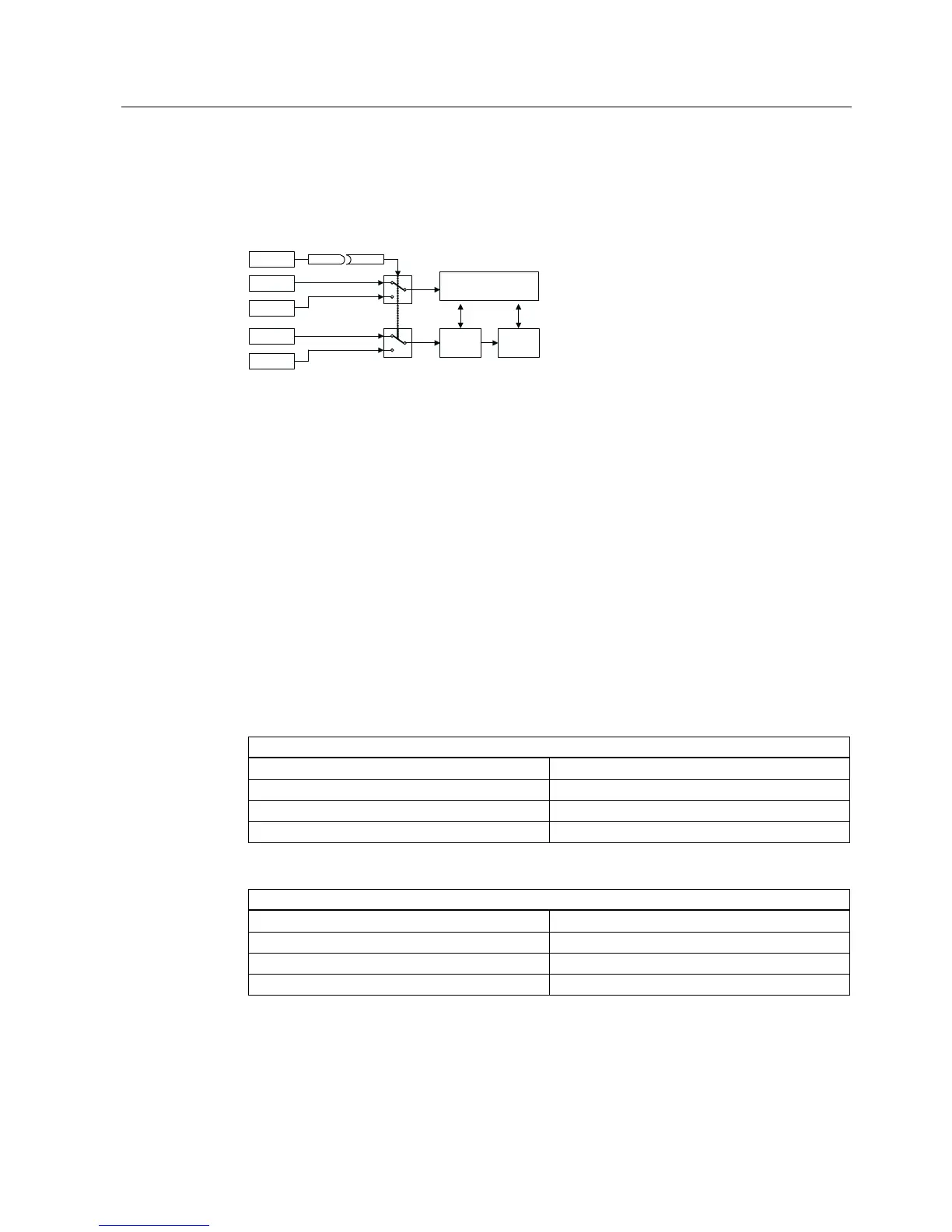
P0700[0] = 2
P0810 = 722.3
0
1
0
1
P0700[1] = 1
P1000[0] = 2
P1000[1] = 1
DI3
OP
&RPPDQGVRXUFH 7HUPLQDO!23
6HWSRLQWIUHTXHQF\VRXUFH $,!023
Motor
control
Terminals
AI
MOP
Sequence control
Setpoint
channel
Figure 8-5 Changing-over between the control and setpoint source
CDS0: Command source via terminals and setpoint source via analog input (AI)
CDS1: Command source via OP and setpoint source via MOP
CDS changeover is realized using digital input 3 (DI3)
Commissioningsteps:
1. Carry-out commissioning for CDS0 (P0700[0] = 2 and P1000[0] = 2)
2. Connect P0810 (P0811 if required) to the CDS changeover source
(P0704[0] = 99, P0810 = 722.3)
3. Copy from CDS0 to CDS1 (P0809[0] = 0, P0809[1] = 1, P0809[2] = 1)
4. Adapt CDS1 parameters (P0700[1] = 1 and P1000[1] = 1)
Drive data set
The drive data set (DDS) contains various setting parameters which are of significance for
the open-loop and closed-loop control of a motor:
Drive and encoder data, e.g.
Select motor type P0300
Rated motor voltage P0304
Main inductance P0360
Select encoder type P0400
Various closed-loop control parameters, e.g.
Fixed frequency 1 P1001
Min. frequency P1080
Ramp-up time P1120
Control mode P1300
 Loading...


