Minimum clearances
If you install the IE Switch in rack devices without forced ventilation or cooling, minimum
clearances must be maintained to neighboring devices or the wall of the enclosure. By keeping
to the minimum clearances, there is then an adequate stream of air for heat dissipation during
operation. Keep to the following minimum clearances to neighboring devices.
Table 5-2 Minimum clearances for installation in rack devices
Minimum clearance to devices below the switch 100 mm
Minimum clearance to devices above the switch 100 mm
Minimum clearance between two SCALANCE XR-300s at an ambient
temperature up to 70 °C without external ventilation
100 mm
Minimum clearance between two SCALANCE XR-300s at an ambient
temperature up to 60 °C without external ventilation
45 mm (1 height unit)
NOTICE
Four-point mounting
If mechanical load is high, the device should be secured at four points. You will find more
detailed information in the section "Mechanical stability in operation".
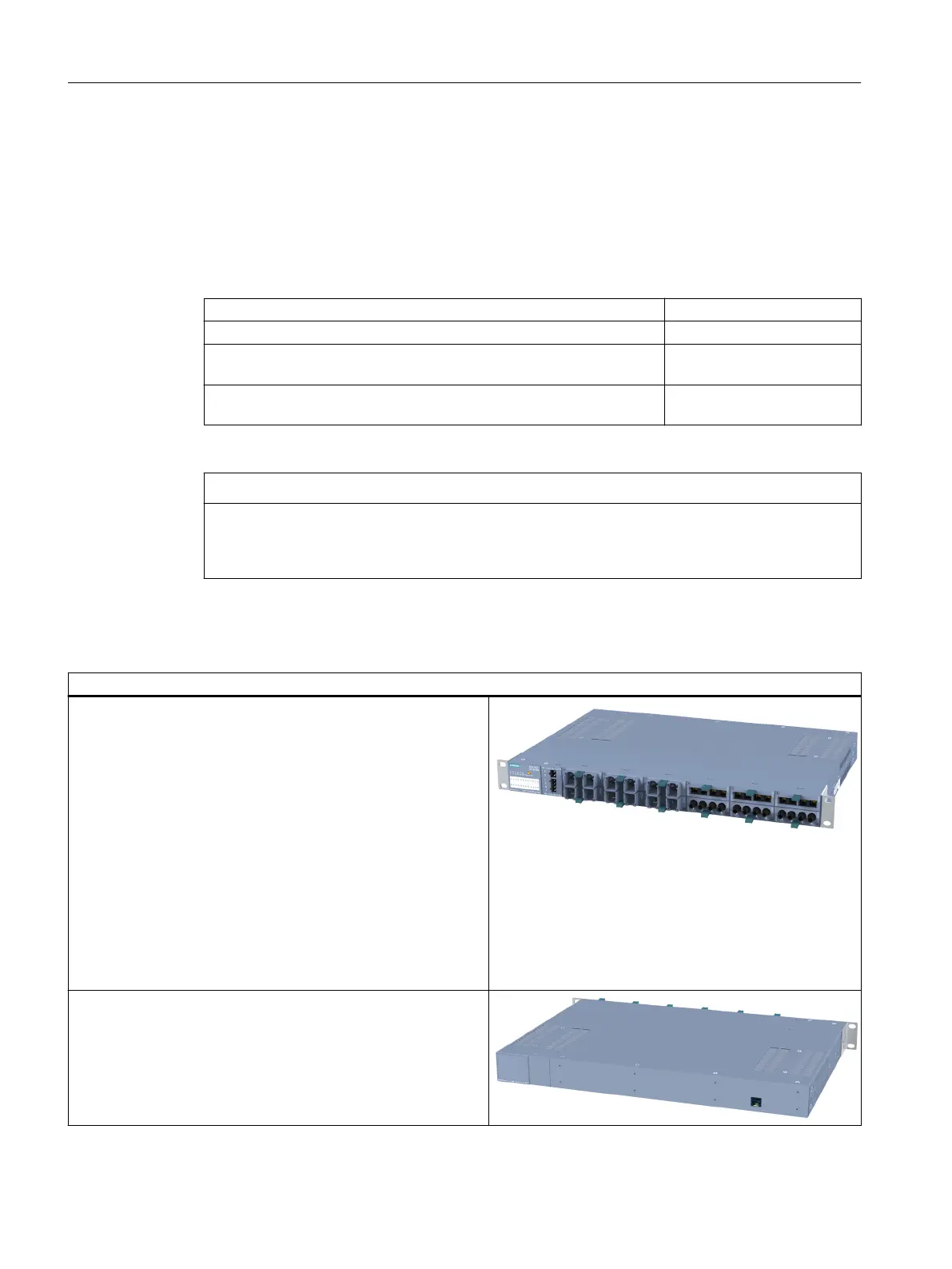
Normal orientation
Normal orientation of the device
● The LED display is on the left of the front panel of the housing.
● To the right of the LED display, the SCALANCE XR-300 has
connectors for the signaling contacts and the power supply.
Note that the SCALANCE XR-300 is available for different
power supplies (100 to 240 VAC and 24 VDC variants).
● The Ethernet ports or the slots for the modules are also on the
front of the housing. Slots for the modules are fitted with
dummy covers.
● The C-PLUG is on the right behind a protective panel secured
with screws.
(For more detailed information, refer to the section on the C-
PLUG in the X-300 operating instructions.)
● The ventilation grilles are on the top, bottom and sides of the
housing.
● On the back of the housing, you will find the diagnostics port
of the device. (For more details, refer to Diagnostics port
XR-300.) On the SCALANCE X-300M EEC, you will also find
the connectors for the signaling contacts and power supply
here.
Installation
5.4 Installing a switch
SCALANCE X-300
106 Operating Instructions, 11/2019, A5E01113043-24

 Loading...