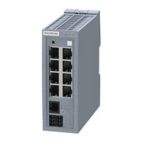
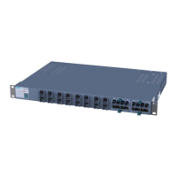
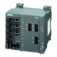
Table 8-90 Power over Ethernet at port P1 to P8
PoE function within a power supply system According to IEEE 802.3af / 802.3at (type 1) for
environment A
Method of PoE power feed Alternative A
(refer to the following table for the pin assignment)
Reserved power per port 15.4 W at port,
of which the following can be used by the PD:
12.95 W
Overall power on all PoE ports Max. 53.2 W
Table 8-91 Electrical isolation
Between ports P1 to P8 No
Between ports P9 to P16 Yes
Between port groups
P1 to P8 and P9 to P16
Yes
Between ports and ground Yes
Between ports and 24 VDC / 230 VAC power input Yes
Table 8-92 Pin assignment of the Ethernet ports of the SCALANCE PoE switch
Pin number / wire
1)
Assignment for data transmis‐
sion
Assignment for power transfer
(PoE).
Alternative A (MDI-X)
Pin 1 RX+ V-
Pin 2 RX- V-
Pin 3 TX+ V+
Pin 4 - -
Pin 5 - -
Pin 6 TX- V+
Pin 7 - -
Pin 8 - -
1)
with 4-wire industrial twisted-pair cables, the wires are connected to pins 1, 2, 3 and 6.
8.8.3 Cable lengths
Table 8-93 Permitted cable lengths (copper cable - Fast Ethernet)
Cable type Accessory (plug, outlet, TP cord) Permitted cable length
IE TP torsion cable with IE FC Outlet RJ-45
+ 10 m TP cord
0 to 45 m
+ 10 m TP cord
with IE FC RJ-45 Plug 180 0 to 55 m
Technical specifications
8.8 XR-300M PoE technical specifications
SCALANCE X-300
198 Operating Instructions, 11/2019, A5E01113043-24
 Loading...
