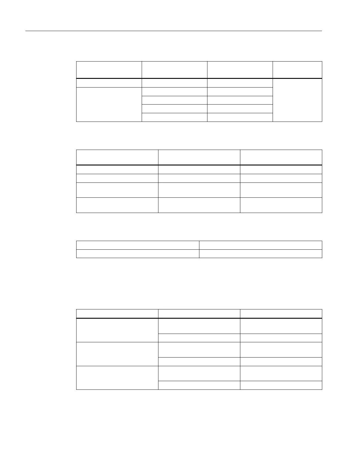
Table 8-61 Electrical data: Signaling contact
Device version
(power supply)
Voltage via signaling con‐
tact
Switching capacity
(resistive load)
Resistor between
F1-F2
24 to 48 VDC 24 VDC max. 0.1 A < 8 Ω
100 to 240 VAC / 60 to
250 VDC
240 VAC max. 5 A
60 VDC max. 0.4 A
125 VDC max. 0.22 A
250 VDC max. 0.11 A
Table 8-62 Plug-in terminal block for connectors of the power supply and signaling contact
Device version
(power supply)
Power supply Signaling contact
1 x 24 to 48 VDC 1 x 4-pin 1 x 2-pin
2 x 24 to 48 VDC 2 x 4-pin 2 x 2-pin
1 x 100 to 240 VAC / 60 to
250 VDC
1 x 3-pin 1 x 3-pin
2 x 100 to 240 VAC / 60 to
250 VDC
2 x 3-pin 2 x 3-pin
Table 8-63 Overvoltage category
General Overvoltage category II
In the application range of EN 60255-27 Overvoltage category III
8.6.3 Cable lengths
Table 8-64 Permitted cable lengths (copper cable - Fast Ethernet)
Cable type Accessory (plug, outlet, TP cord) Permitted cable length
IE TP torsion cable with IE FC Outlet RJ-45
+ 10 m TP cord
0 to 45 m
+ 10 m TP cord
with IE FC RJ-45 Plug 180 0 to 55 m
IE FC TP Marine Cable
IE FC TP Trailing Cable
IE FC TP Flexible Cable
with IE FC Outlet RJ-45
+ 10 m TP cord
0 to 75 m
+ 10 m TP cord
with IE FC RJ-45 Plug 180 0 to 85 m
IE FC TP standard cable with IE FC Outlet RJ-45
+ 10 m TP cord
0 to 90 m
+ 10 m TP cord
with IE FC RJ-45 Plug 180 0 to 100 m
Technical specifications
8.6 XR-300M EEC technical specifications
SCALANCE X-300
184 Operating Instructions, 11/2019, A5E01113043-24

 Loading...