PS2
L1 L2
L1 M1 L2M2 L1 M1 L2M2
F1
F2
L1 L2
L1 M1 L2M2F1
F2 L1 M1 L2M2
PS1
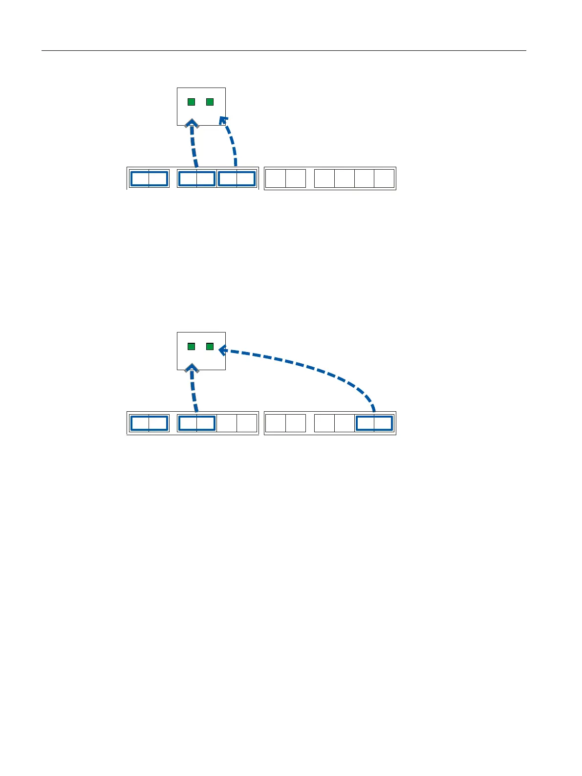
Figure 6-6 Assignment of the LED display to the pins for redundant power supply with devices with two
power supply units
● If the power supply fails at pins L1/M1, this is indicated by LED L1.
● If the power supply fails at pins L2/M2, this is indicated by LED L2.
Connecting a redundant power supply to 2 power supply units
To connect the power supplies, use pins L1/M1 of the left terminal block "PS1" and pins L2/M2
of the right terminal block "PS2".
PS2
L1 L2
L1 M1 L2M2 L1 M1 L2M2
F1
F2
L1 L2
L1 M1 L2M2F1
F2 L1 M1 L2M2
PS1
Figure 6-7 Assignment of the LED display to the pins for redundant power supply with devices with two
power supply units.
● If the power supply fails at pins L1/M1, this is indicated by LED L1.
● If the power supply fails at pins L2/M2, this is indicated by LED L2.
It would also be possible to use the L1/M1 pins of the right terminal block. In this case, however,
identification of the terminal block involved from the LED display is not immediately obvious.
Connecting
6.6 Power supply
SCALANCE X-300
134 Operating Instructions, 11/2019, A5E01113043-24

 Loading...