EasyManuals Logo

Siemens SIMATIC ET 200SP User Manual

Siemens SIMATIC ET 200SP
140 pages
To Next Page IconTo Next Page
To Previous Page IconTo Previous Page
Page #36 background imageLoading...
Page #36 background image
Installing
4.1 Basics
CPU 1515SP PC (F)
36 Manual, 05/2017, A5E32701806-AC
Minimum clearances
Maintain the following minimum clearances when installing or dismantling the
CPU 1515SP PC (F).
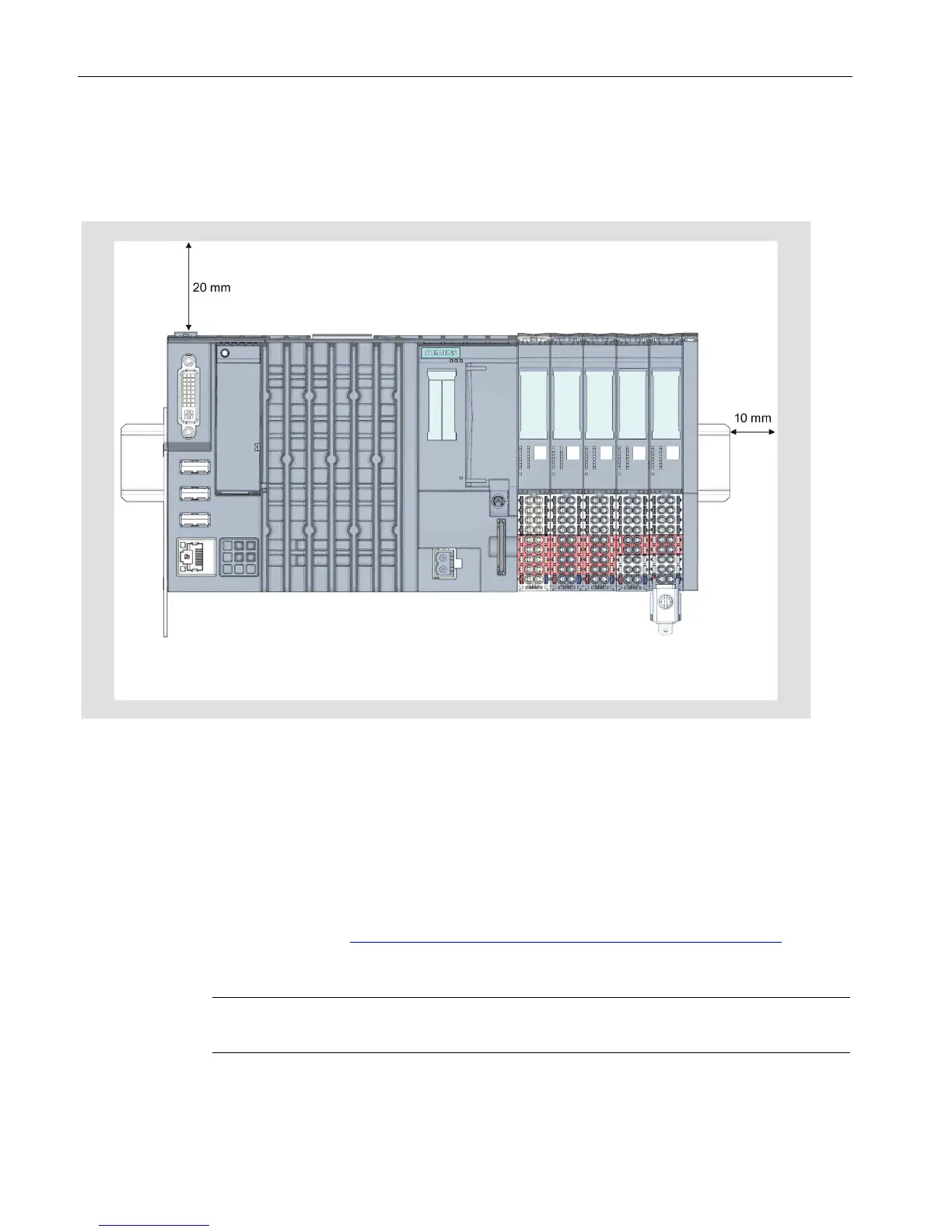
Figure 4-1 Minimum clearances
Installation rules
After the CPU 1515SP PC (F) there is a BaseUnit BU..D with incoming supply voltage L+
(light terminal box).
This is followed by BaseUnits BU..B (with dark-colored terminal box).
The respective corresponding I/O modules can be connected to the BaseUnits.
Suitable combinations of BaseUnits and I/O modules can be found in the ET 200SP
System Manual (http://support.automation.siemens.com/WW/view/en/84133942).
The server module completes the installation.
Note
Only install the CPU
1515SP PC (F) when the power supply is switched off.

Table of Contents

Other manuals for Siemens SIMATIC ET 200SP

Questions and Answers:

Question and Answer IconNeed help?

Do you have a question about the Siemens SIMATIC ET 200SP and is the answer not in the manual?

Siemens SIMATIC ET 200SP Specifications

General IconGeneral
System TypeDistributed I/O System
MountingDIN Rail
Communication ProtocolPROFINET, PROFIBUS
IP RatingIP20
CategoryI/O Systems
Supply Voltage24 V DC
ModularityYes
Hot SwappingYes
Storage Temperature-40°C to +70°C
Digital InputsYes
Digital OutputsYes
Analog InputsYes
Analog OutputsYes
Communication InterfacePROFINET, PROFIBUS
Number of ModulesUp to 64
Relative Humidity5 to 95% (non-condensing)
Operating Temperature-25°C to +60°C

Related product manuals