Installation and connection
4.3 Connecting the HMI device
TP 270, OP 270, MP 270B (WinCC flexible)
4-6 Operating Instructions, Edition 03/2004, 6AV6691-1DD01-0AB0
4.3.2 Interfaces
Interfaces
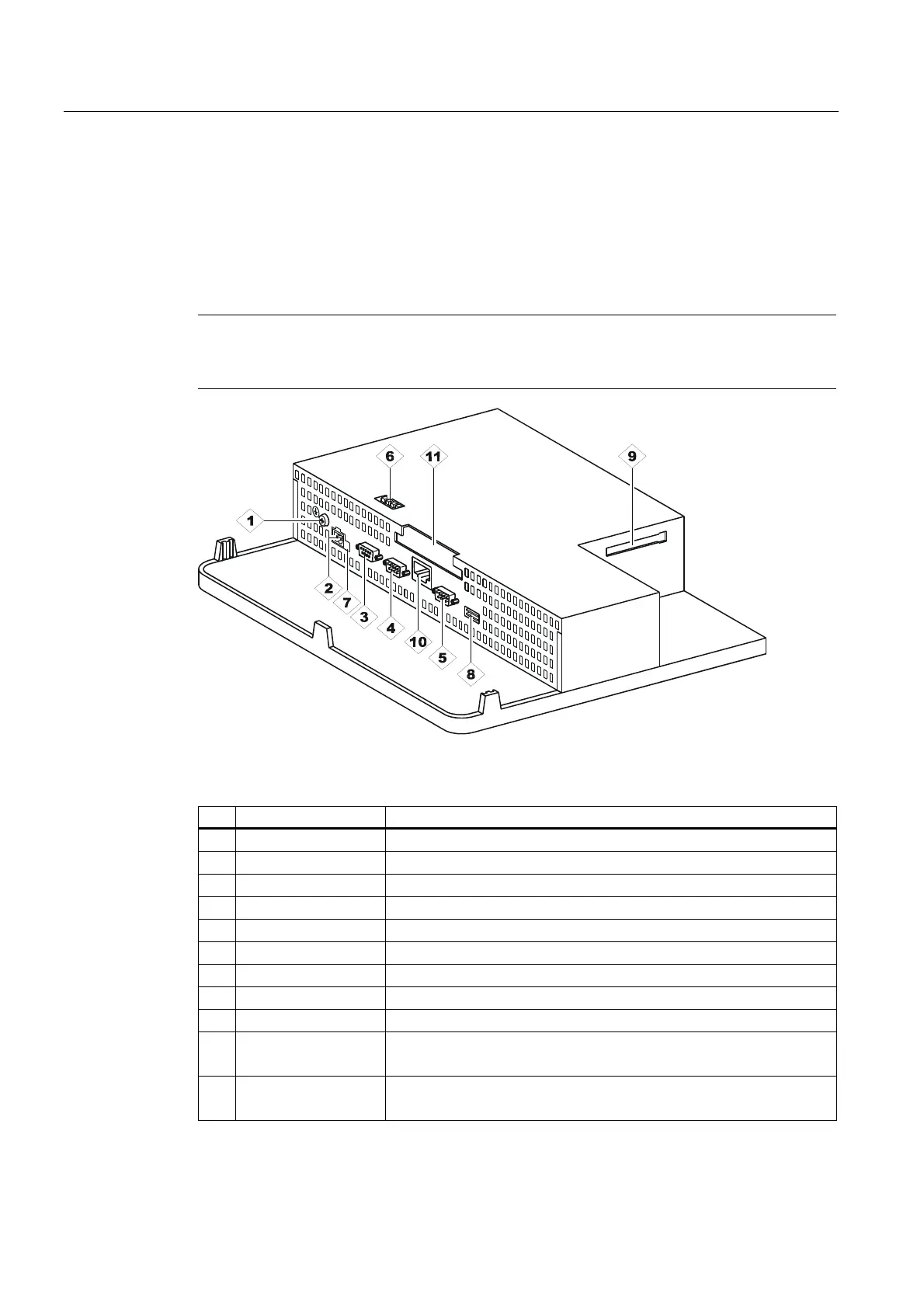
The figure below illustrates the arrangement of the interfaces on underside of the HMI
device, exemplified by the MP 270B 10" Keys.
Notice
In the case of the TP 270 and OP 270, the interfaces for the PC card and Ethernet interface
on-board are missing. To enable an Ethernet connection, the devices require a CF card.
Figure 4-1 Arrangement of the interfaces (example, MP 270B 10" Keys)
No. Description Application
1 Ground connection For connection to rack ground
2 Power supply Connection to power supply +24 V DC)
3 Interface IF1B RS 422/RS 485 (floating) for PLC, PC, PU
4 Interface IF1A RS 232 for PLC
5 Interface IF2 RS 232 for PC, PU, printer
6 Switch To configure interface IF1B
7 Battery connection Connection for optional backup battery
8 USB interface Connection for external keyboard, mouse, etc.
9 Slot B For CF card
10 Ethernet interface
(for MP 270B only)
Connection of an RJ45 Ethernet line
11 Slot A
(for MP 270B only)
For PC card