Maintenance and servicing
6.5 Forming the DC link capacitors
Cabinet Modules NEMA
326 Manual, 04/2014, A5E03586450A
The date of manufacture can be determined as follows:
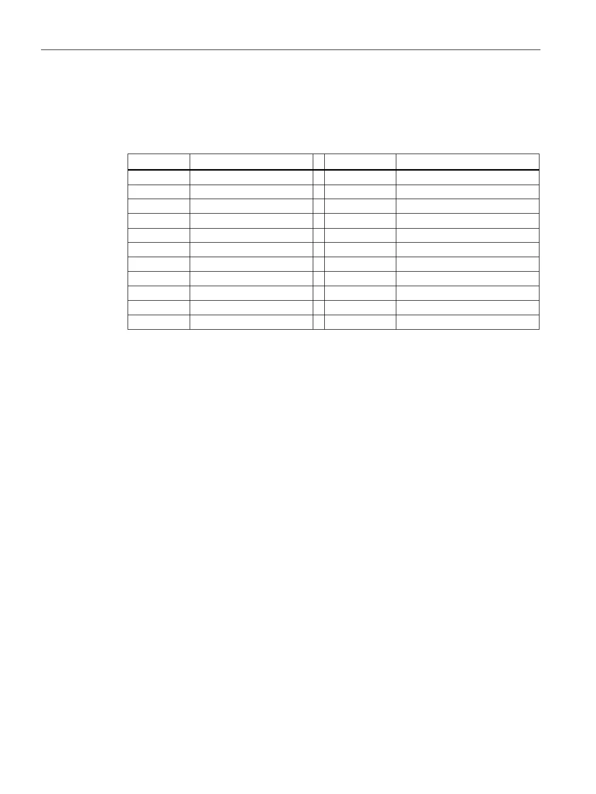
Table 6- 5 Production year and month
D 2013 D December
Procedure in the event of repair or replacement
A replacement Line Module or Motor Module or the corresponding replacement power block
has to be re-formed after being in storage for a period of more than two years.
The DC link capacitors are re-formed by applying the rated voltage without load for at least
30 minutes.
To do this, the DC link must be precharged (i.e. the Line Modules switched on), while the
controller for the existing Motor Modules must not be enabled for the specified length of time.
Procedure for re-forming outside the drive assembly
Replacement power units which have to be held ready for immediate use in the event of
repair or replacement can also be re-formed individually and outside the drive assembly.
For this, the equipment must be connected to the forming circuits described in the following.
Components for the forming circuit (recommendation)
● 1 fuse switch 3-phase 400 V / 10 A or 690 V / 10 A
● 6 incandescent lamps 120 V / 50 W for a line voltage of 380 to 480 V 3 ph. AC, where 2
incandescent lamps must be connected in series in each supply phase.
Alternatively, use 3 resistors of 1 kΩ / 100 W each (e.g. GWK150J1001KLX000 from
Vishay) instead of the incandescent lamps.

 Loading...


