Connecting the positioner
1. Connect a suitable current or voltage source. The positioner is now in "P manual mode". The
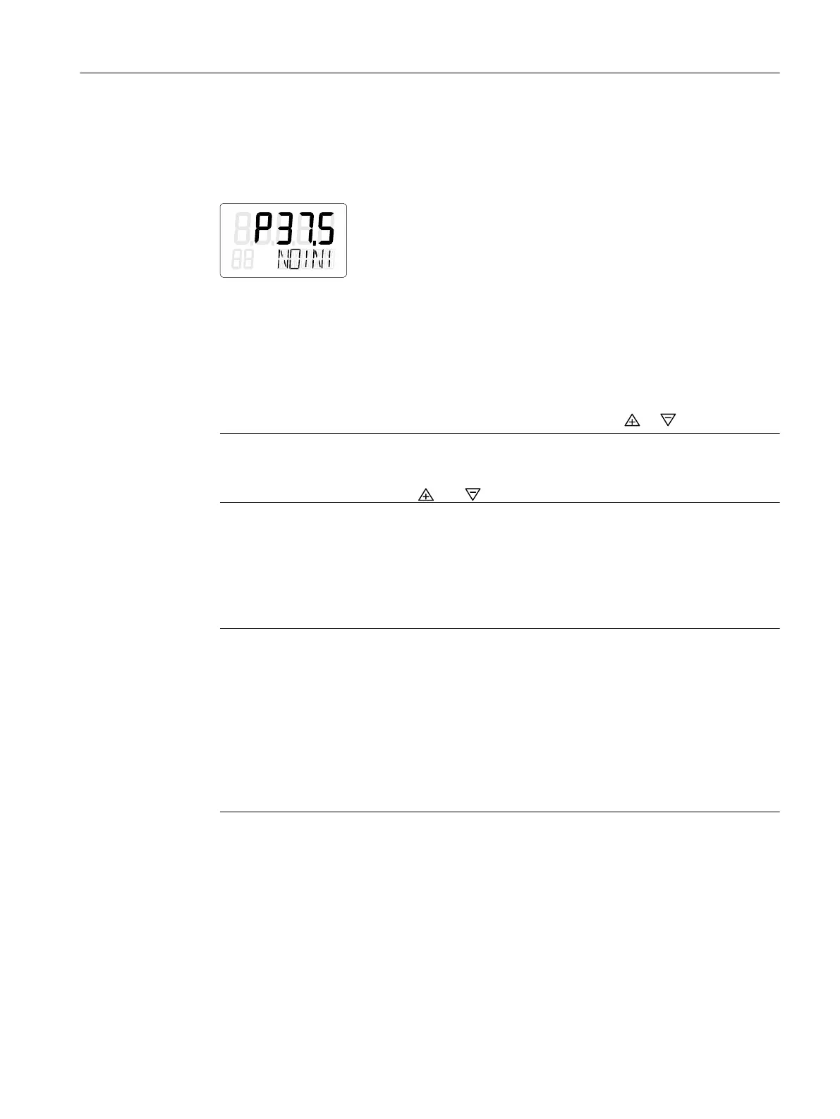
current potentiometer voltage (P) in percent is shown in the upper line of the display, e.g.:
'P37.5', and 'NOINI' flashes in the bottom line:
2. Connect the actuator and the positioner to the pneumatic lines.
3. Supply the pneumatic auxiliary power to the positioner.
Setting the actuator
1. Check whether the mechanical unit can be moved freely in the entire travel range. Move the
actuator to the respective end position for this purpose using the or button.
Note
End position
By simultaneously pressing the and buttons, you reach the end position faster.
2. Now move the actuator to the horizontal position of the lever.
3. A value between 'P48.0' and 'P52.0' is shown on the display.
4. If a value beyond this value range is shown on the display, you must move the friction clutch.
Move the friction clutch until a value between 'P48.0' and 'P52.0' is reached. The closer this
value is to 'P50.0', the more accurately the positioner determines the stroke travel.
Note
For device versions with flameproof enclosure
The inner friction clutch is fixed. Therefore, only move the outer friction clutch. This also
applies when using an internal NCS module.
The following applies to device versions without flameproof enclosure with internal NCS
module 6DR4004-5L.:
The inner friction clutch has no function. This means you should only adjust the adjustment
wheel of the magnet clamp; see section "Internal NCS modules (iNCS) 6DR4004-5L and
-5LE (Page 70)". Condition: The '1.YFCT' type of actuator (Page 142) parameter is set.
See also
Mounting to linear actuator (Page 42)
Device components (Page 28)
Installing the optional modules (Page 53)
Commissioning
7.6 Commissioning linear actuators
SIPART PS2 with PROFIBUS PA
Operating Instructions, 05/2019, A5E00127926-AC 119

 Loading...


