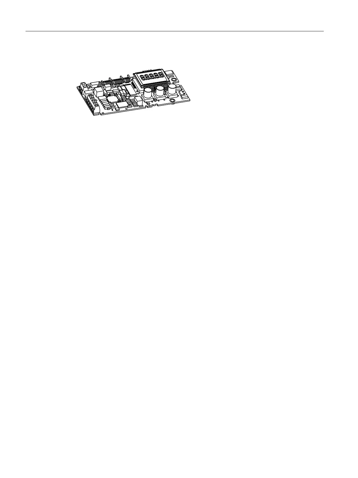
3.3.3 Basic electronics
Figure 3-8 Basic electronics, schematic representation
The basic electronics contains:
● CPU
● Memory
● Analog-to-digital converter
● Display
● Buttons
● Terminal strips to connect the option module to the basic electronics
3.4 Functional principle
Control loop
The electropneumatic positioner forms a control loop with the pneumatic actuator:
● The actual value x represents the position of the actuator spindle for linear actuators or the
position of the actuator shaft for part-turn actuators.
● The higher-level control loop provides the setpoint w.
The stroke or rotary movement of the actuator is transferred to a potentiometer using suitable
attachments, positioner shaft and a backlash-free, switchable gear drive, and then to the
analog input of the microcontroller.
The current position can also be forwarded to the positioner using an external sensor. A Non
Contacting Position Sensor (NCS) is used to record the stroke or rotary angle directly on the
actuator.
The microcontroller:
● Corrects the angle error of the shaft pick-up if necessary.
● Compares the potentiometer voltage as actual value x with setpoint w.
● Calculates the manipulated variable increments ±∆y.
The piezo-controlled inlet or exhaust air valve is opened depending on the magnitude and
direction of the control deviation (x-w). The actuator volume integrates the controller increment
for the actuating pressure y which is proportional to the drive rod or the drive shaft. This
controller increment changes the actuating pressure until the control deviation becomes zero.
Description
3.4 Functional principle
SIPART PS2 with PROFIBUS PA
30 Operating Instructions, 05/2019, A5E00127926-AC

 Loading...


