3.3 Device components
3.3.1 Overview of device components
-
8
7
82
6
81
10
9
Binary
input 1
+
24V
33
Positioner
Transmission ratio selector
Shut
Down
input
BUS
Shut Down
disabled
90
O
O
Jumper
Shut Down
enabled
r
r
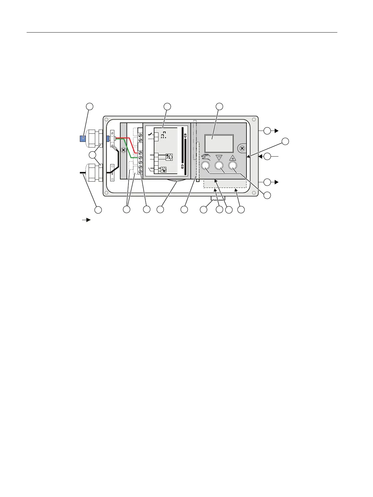
Arrowhead means: Turn the device to see the corresponding view
① Bus cable ⑩ Restrictor Y1 for single-acting actuators
② Wiring diagram on module cover ⑪ Restrictor Y1 for double-acting actuators
③ Display ⑫ Exhaust air outlet with a sound absorber
④ Purging air selector ⑬ Transmission ratio selector
⑤ Output: Actuating pressure Y1 ⑭ Friction clutch adjustment wheel
⑥ Input: Supply air ⑮ Basic electronics
⑦ Output: Actuating pressure Y2 ⑯ Connecting terminals of option modules
⑧ Buttons ⑰ Shield connection (only with polycarbonate
enclosure)
⑨ Restrictor Y2 for double-acting actuators ⑱ Cable gland
Figure 3-6 View of the positioner (cover open; polycarbonate enclosure)
Description
3.3 Device components
SIPART PS2 with PROFIBUS PA
28 Operating Instructions, 05/2019, A5E00127926-AC
 Loading...


