The following table shows the pneumatic connection versions for different actuator types,
regulating action and safety position after an auxiliary power supply failure.
Actuator type Response to failure of auxiliary power: The ac‐
tuator moves into safety position
Fail in place, order suffix F01
Failure of electrical
auxiliary power
Failure of pneumatic
auxiliary power
Failure of electrical
auxiliary power
Failure of pneumatic
auxiliary power
Single-acting Y1 = vented Y1 = vented Y1 = closed Y1 = closed
Double-acting Y1 = pressurized
Y2 = vented
Y1 = closed
Y2 = closed
Y1 = closed
Y2 = closed
Y1 = closed
Y2 = closed
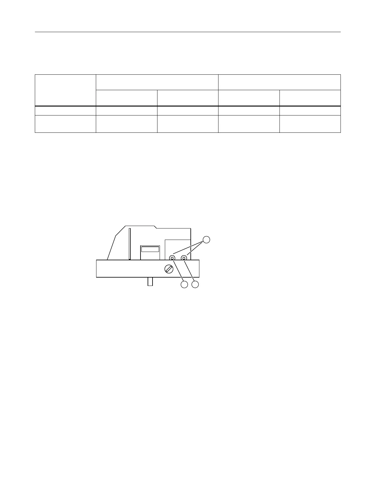
5.4 Restrictors
● Reduce the air output to achieve travel times of T > 1.5 s for small actuators. Use restrictors
Y1 ① and Y2 ② for this purpose.
● When turned clockwise, they reduce the air output and finally shut it off.
● In order to set the restrictors, we recommend closing them and then opening slowly.
● In case of double-acting valves, ensure that both restrictors have approximately the same
setting.
① Restrictor Y1
② Restrictor Y2, only in the version for double-acting actuators *)
③ Hexagon socket-head screw 2.5 mm
Figure 5-13 Restrictors
*) Restrictor Y2 ② is not active for single-acting Fail in Place F01
See also
Sequence of automatic initialization (Page 111)
Connect
5.4 Restrictors
SIPART PS2 with PROFIBUS PA
Operating Instructions, 05/2019, A5E00127926-AC 95

 Loading...


