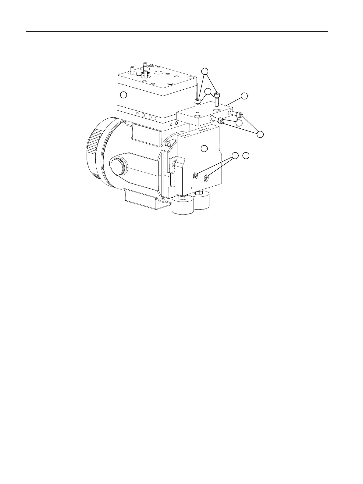
3. Apply light pressure to the lock washers ⑧. The screws are tightened later.
4. Fasten the connection block ⑨ to the booster with 2 screws ⑫ and 2 lock washers ⑬.
5. Fasten the connection block ⑨ to the manometer block ⑥ with 2 screws ⑩ and 2 lock
washers ⑪.
6. Check whether the O-rings are in the manometer block. There are two O-rings in the single-
acting version. There are three O-rings with the double-acting version.
7. Apply light pressure to the lock washers ⑬. The screws are tightened later.
C. Tighten screws
Tighten the screws in the following sequence:
1. Screws ⑦ which are used to fasten the manometer ⑥ to the positioner.
2. Screws ⑫ which are used to fasten the connection block ⑨ to the booster.
3. Screws ⑩ which are used to fasten the connection block ⑨ to the manometer ⑥.
4. Mount the positioner on the actuator as described in:
– Mounting to linear actuator (Page 42)
– Mounting to part-turn actuator (Page 47)
5. Use the existing interfaces on the booster.
Booster
E.5 Booster mounting, flameproof enclosure
SIPART PS2 with PROFIBUS PA
344 Operating Instructions, 05/2019, A5E00127926-AC
 Loading...


