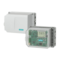
1. Strip off 85 mm of the cable jacket (with the shielding) and 5 mm of the insulated conductor
insulation of the cable ②.
2. Remove the enclosure cover of the positioner 6DR5910-..., by loosening the four mounting
screws.
3. Insert the prepared cable ② through the cable entry of the positioner.
4. Tighten the cable gland ③.
5. Connect the conductors of the cable ② to the terminals ④ of the positioner according to the
connection diagram ⑤.
6. Fasten the enclosure cover with the four mounting screws.
7. Assign a maximum of five positioner (-channels) to the male connector Burndy B50 ⑥ in the
field distributor ①.
Connecting multiple positioners (Page 356)
8. Plug the male connector Burndy B50 ⑥ into the Burndy B50 ⑧ socket on the QRL
module ⑦.
9. Specify the number of channels for each PROFIBUS line and set the coding bridges on the
PA module accordingly.
Connecting 19" slide-in modules (Page 358)
PA cable connection for bus connection (Page 357)
Result
The remote electronics in the 19" slide-in module is connected to the positioner 6DR5910-...
Positioner with remote control electronics
F.2 19" slide-in module
SIPART PS2 with PROFIBUS PA
Operating Instructions, 05/2019, A5E00127926-AC 355
 Loading...


