Auxiliary Functions
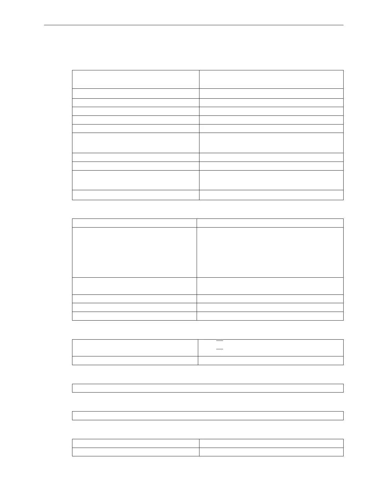
Operational Measured Values
Operational measured values for voltages U
a
, U
b
, U
c
, U
d
, U
e
, U
f
in V secondary
Range 10 % to 120 % of U
N
Tolerance 0,2 % of measured value or ±0,2 V ±1 Digit
Power Angle Δα
Range –180° to +180°
Tolerance 0,5°
Range
8
1
/
2
digits (28 Bit) for VDEW protocol
9
1
/
2
digits (31 Bit) in the unit
Tolerance 1 % ± 1 Digit
Operating measured values for frequency f1, f2, Δf in Hz
Range 40 Hz < f < 65 Hz at f
N
= 50/60 Hz
12 Hz < f < 20 Hz at f
N
= 16.7 Hz
Tolerance 10 mHz at U = U
N
, f = f
N
± 10 %
Analog Outputs (optional)
Number
max. 2
Possible measured values ΔU; Δf; Δα of the synchronism function in %
IΔUI; IΔfI; IΔαI of the synchronism function in %
U1 of the synchronism function in %
U2 of the synchronism function in %
f1 of the synchronism function in %
f2 of the synchronism function in %
Range 0.0 mA to 22.5 mA or
4.0 mA to 22.5 mA
Minimum threshold (limit of validity) 0.0 mA to 5.0 mA (Increments 0.1 mA)
Maximum threshold 22.0 mA (fixed)
Configurable reference value 20 mA 10.0 % to 1000.0 % (Increments 0.1 %)
Local Measured Values Monitoring
Voltage sum
U1 +(–U1) = 0
U2 +(–U2) = 0
Voltage Phase Sequence Clockwise (L1L2L3)/ counter-clockwise (L1L3L2)
Fault Event Recording
Indications memory for the last 8 fault cases (max. 600 indications)
Operational Messages (Buffer: Event Log)
Maximal memorization of 200 messages, time resolution 1 ms
Time Allocation
Resolution for Event Log (Operational Indications)
1 ms
Resolution for Fault Log (Fault Indications) 1 ms
4.12
Technical Data
4.12 Auxiliary Functions
SIPROTEC 4, 7VE61 and 7VE63, Manual 217
C53000-G1176-C163-3, Edition 10.2017

 Loading...


