Under the assumption that apparent power is reduced to the same degree, turbine-driven generators can, as a
rule, be continuously operated down to 95 % of nominal frequency. However, for inductive consumers, the
frequency reduction not only means greater current consumption but also endangers stable operation. For
this reason, only a short-time frequency reduction down to about 48 Hz (for f
N
= 50 Hz) or 58 Hz (for f
N
= 60
Hz) is permissible.
A frequency increase can, for example, occur due to a load shedding or malfunction of the speed regulation
(e.g. in a stand-alone system). In this way, the frequency increase protection can, for example, be used as
overspeed protection.
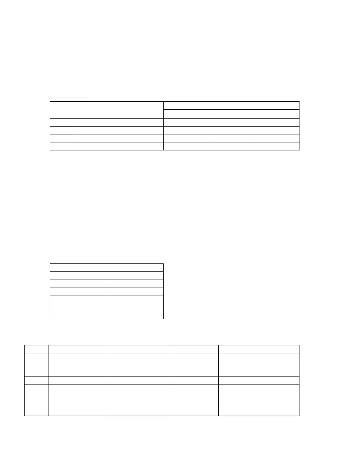
Setting example:
Stage Cause Settings
for f
N
= 50 Hz for f
N
= 60 Hz Delay
f1 Disconnection from the network 48.00 Hz 58.00 Hz 1.00 s
f2 Shutdown 47.00 Hz 57.00 Hz 6.00 s
f3 Warning 49.50 Hz 59.50 Hz 20.00 s
f4 Alarm or tripping 52.00 Hz 62.00 Hz 10.00 s
Time Delays
The delay times T f1 to T f4 entered at addresses4204, 4207, 4210 and 4213) allow the frequency stages
to be graded. The set times are additional delay times not including the operating times (measuring time,
dropout time) of the protective function.
Minimum Voltage
Address 4215 Umin is used to set the minimum voltage which if undershot, frequency protection is blocked. A
value of approx. 65 % U
N
is recommended. The parameter value is based on phase-to-phase voltages. The
minimum voltage threshold can be deactivated by setting this address to 0.
Measurement Input
The parameter 4220 MEAS. INPUT establishes which of the 6 voltage inputs (Ua to Uf) of the device the
frequency measurement is to refer to. The following allocation applies between voltage input and device
connections:
Voltage input
Device connections
Ua Q1, Q2
Ub Q3, Q4
Uc Q5, Q6
Ud Q7, Q8
Ue Q9, Q10
Uf Q11, Q12
Settings
Addr.
Parameter Setting Options Default Setting Comments
4201 O/U FREQUENCY OFF
ON
Block relay
OFF Over / Under Frequency Protection
4202 f1 PICKUP 40.00 .. 65.00 Hz 48.00 Hz f1 Pickup
4203 f1 PICKUP 40.00 .. 65.00 Hz 58.00 Hz f1 Pickup
4204 f1 PICKUP 12.00 .. 20.00 Hz 16.10 Hz f1 PICKUP
4205 T f1 0.00 .. 600.00 sec 1.00 sec T f1 Time Delay
4206 f2 PICKUP 40.00 .. 65.00 Hz 47.00 Hz f2 Pickup
2.6.3
Functions
2.6 Frequency Protection
90 SIPROTEC 4, 7VE61 and 7VE63, Manual
C53000-G1176-C163-3, Edition 10.2017

 Loading...


