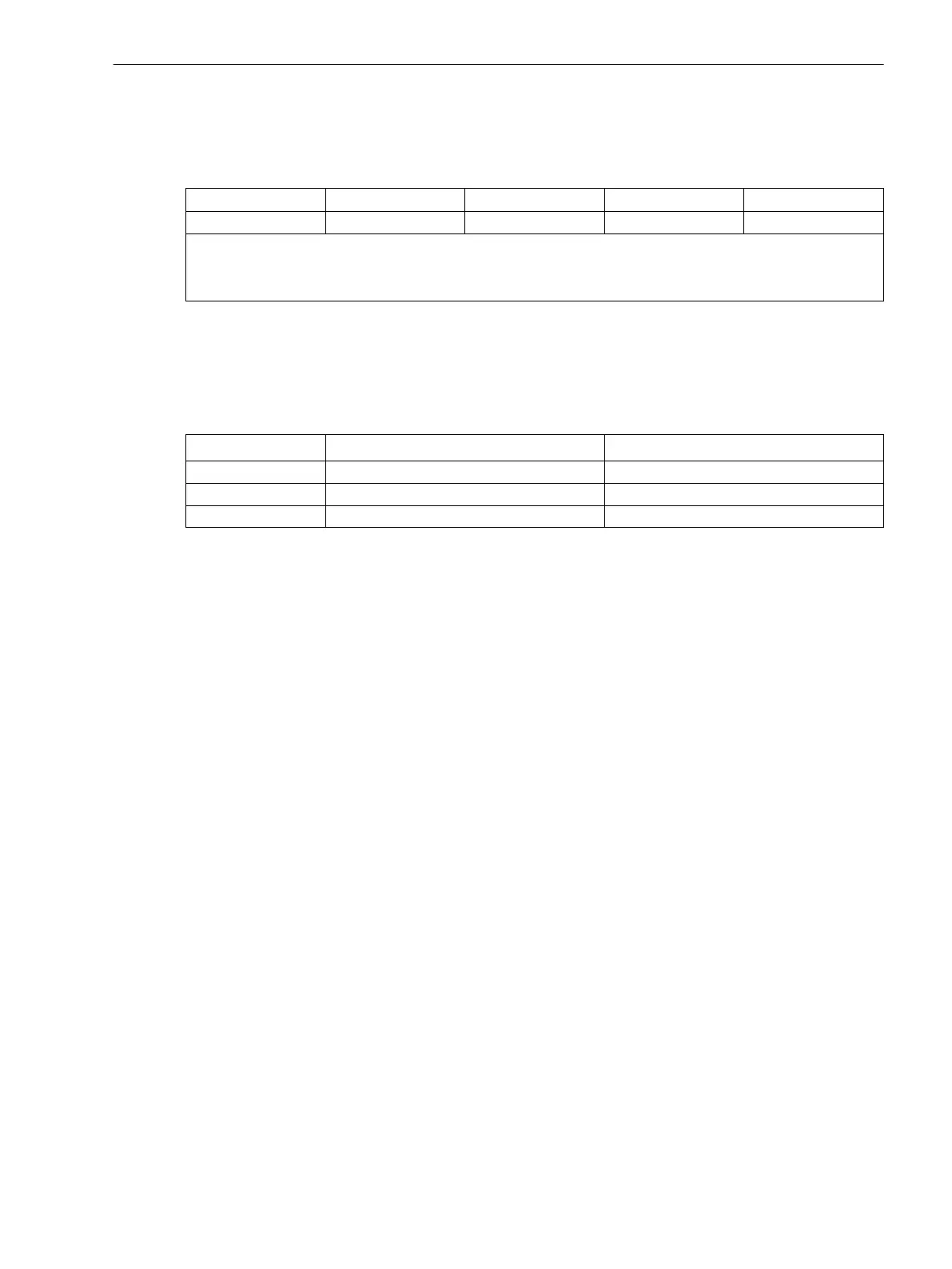
Pickup voltages of the BI6
Table 3-12 Jumper setting for the Pickup voltages (DC voltage) of the binary inputs BI6 on the C–I/O-8
board
Binary Inputs Jumper
19 V Threshold
1)
88 V Threshold
3)
176 V Threshold
3)
BI6 X21 1–2 2–3 3–4
1)
Factory settings for devices with rated power supply voltages of DC 24 V to 125 V
2)
Factory settings for devices with rated power supply voltages of DC 110 to 220 V and AC 115 V to 230 V
3)
Use only with control voltages 220 V or 250 V
Jumpers X71, X72 and X73 on the C–I/O-8 board serve to set the bus address. The jumpers must not be
changed. The following table lists the jumper presettings.
Bus address
Table 3-13 Jumper settings of the Bus address on the input/output board C-I/O-8
Jumper
Housing size
1
/
3
Housing size
1
/
2
X71 2–3 (L) 2–3 (L)
X72 2–3 (L) 2–3 (L)
X73 1–2 (H) 1–2 (H)
Interface Modules
Austausch von Schnittstellenmodulen
The interface modules are located on the C–CPU-2 board ((1) in Figure 3-2 and Figure 3-3). The following
figure shows the PCB with location of the modules.
Figure 3-2
3.1.2.4
Mounting and Commissioning
3.1 Mounting and Connections
SIPROTEC 4, 7VE61 and 7VE63, Manual 155
C53000-G1176-C163-3, Edition 10.2017

 Loading...


