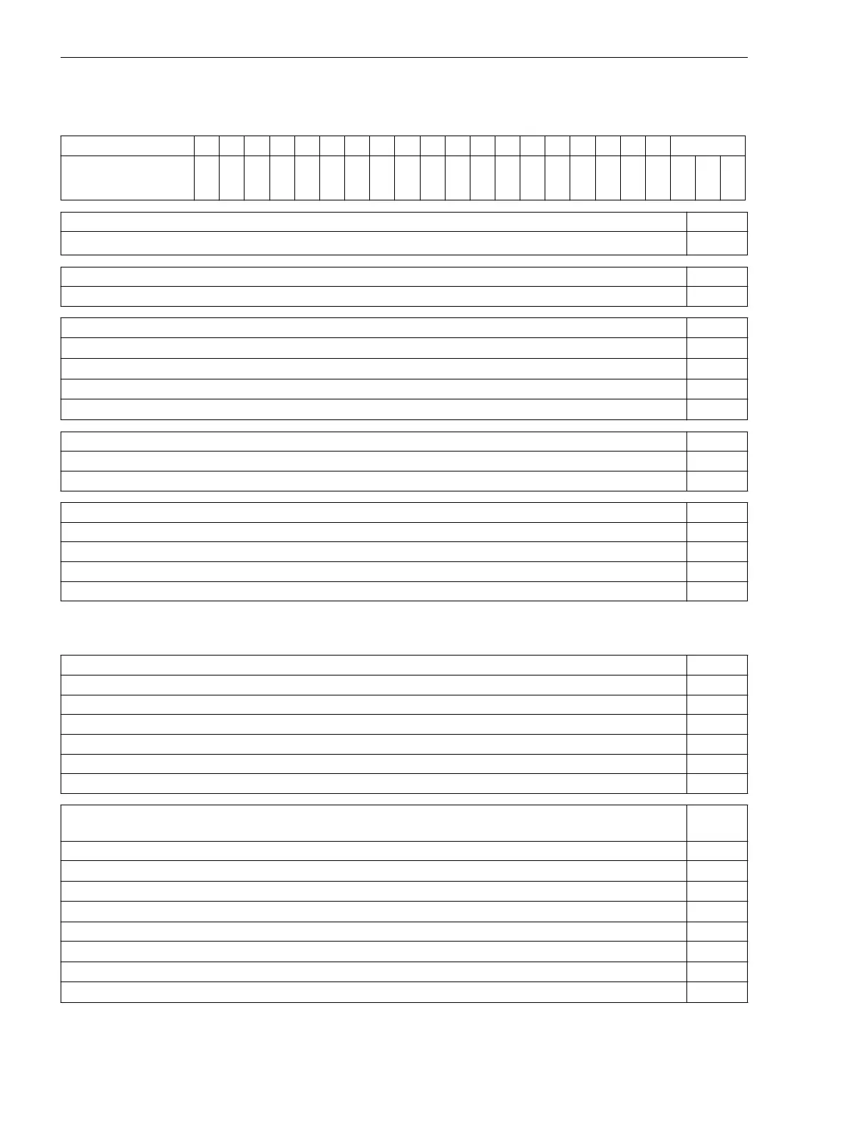
Ordering Information 7VE61
6 7 8 9 10 11 12 13 14 15 16 Zusatz
Multifunctional
Paralleling Device
7 V E 6 1 — — 0 +
Housing, Binary Inputs and Outputs Pos. 6
Housing
1
/
3
19”, 6 BI, 9 BO, 1 live status contact
1
Nominal Device Current Pos. 7
without 0
Auxiliary Voltage (Power Supply, Pickup Threshold of Binary Inputs) Pos. 8
DC 24 V bis 48 V, Binary Input Threshold DC 19 V
3)
2
DC 60 V bis 125 V
1)
, Binary Input Threshold DC 19 V
3)
4
DC 110 V bis 250 V
1)
, AC 115 V bis 230 V, Binary Input Threshold DC 88V
3)
5
DC 220 V bis 250 V
1)
, AC 115 V bis 230 V, Binary Input Threshold DC 176 V
3)
6
Construction Pos. 9
Surface-mounting housing for panel, 2-tier terminals top / bottom B
Flush mounting housing, screw-type terminals (direct connection / ring and spade lugs) E
Region-specific default / language settings and function versions Pos. 10
Region DE, 50 Hz, IEC, German Language (language can be changed) A
Region World, 50 / 60 Hz, IEC / ANSI, Language English (language can be changed) B
Region US, 60 Hz, ANSI, American English Language (language can be changed) C
Region World, 50 / 60 Hz, IEC / ANSI, Spanish Language (language can be changed) E
1)
with plug-in jumper one of the 2 voltage ranges can be selected
2)
for each binary input the pickup threshold ranges are interchangeable via plug-in jumpers
System interfaces (Port B)
Pos. 11
None 0
System port, IEC protocol, electrical RS232 1
System port, IEC protocol, electrical RS485 2
System port, IEC protocol, optical 820 nm, ST-connector 820 nm 3
Analog Outputs 2 x 0 to 20 mA or 4 to 20 mA 7
For further protocols see Additional Information in the following L 9
Additional information L for further protocols (port B) Supple-
mentary
System port, Profibus DP slave, electrical RS485 +L 0 A
System port, Profibus DP slave, optical 820 nm, twin ring, ST-connector
1)
+L 0 B
System port, Modbus RTU, electrical RS485 +L 0 D
System port, Modbus RTU, optical 820 nm, twin ring, ST-connector
1)
+L 0 E
System Port, DNP 3.0, electrical RS485 +L 0 G
System Port, DNP 3.0, optical 820 nm, ST-connector
1)
+L 0 H
IEC 61850, electrical with EN100, with RJ45-connector +L 0 R
IEC 61850, optical with EN100, with ST-connector
2)
+L 0 S
1)
If the 9th position is = “B” (panel surface mounting), then the device must be ordered with the RS485–Inter-
face and a separate Optical Fibre-converter
A.1
Ordering Information and Accessories
A.1 Ordering Information 7VE61
224 SIPROTEC 4, 7VE61 and 7VE63, Manual
C53000-G1176-C163-3, Edition 10.2017

 Loading...


