Settings
Addresses which have an appended “A” can only be changed with DIGSI, under “Additional Settings”.
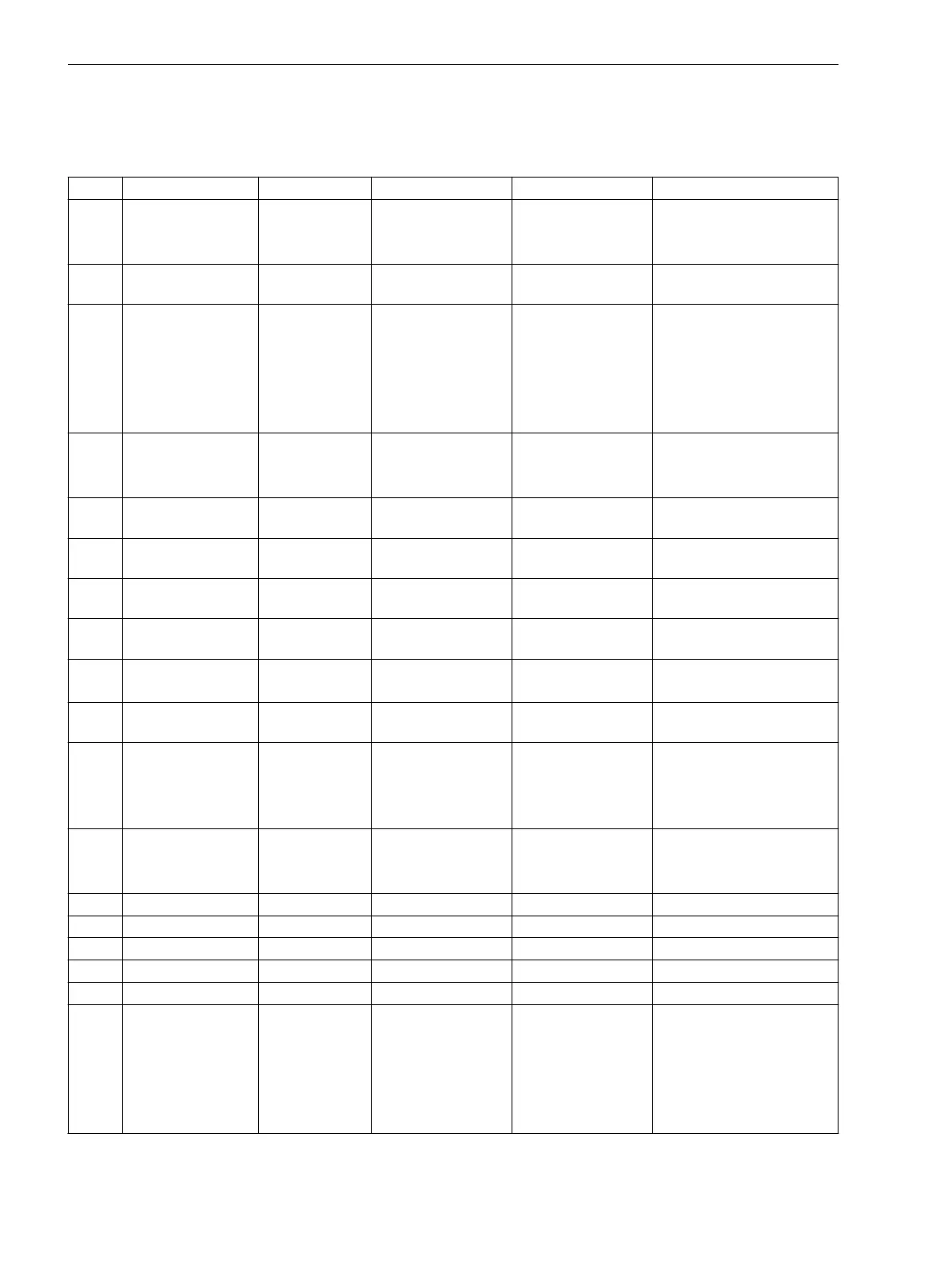
Addr. Parameter Function Setting Options Default Setting Comments
270 Rated Frequency P.System Data 1 50 Hz
60 Hz
16,7 Hz
50 Hz Rated Frequency
280 TMin TRIP CMD P.System Data 1 0.01 .. 32.00 sec 0.15 sec Minimum TRIP Command
Duration
302 CHANGE Change Group Group A
Group B
Group C
Group D
Binary Input
Protocol
Group A Change to Another Setting
Group
401 WAVEFORM-
TRIGGER
Osc. Fault Rec. Save w. Pickup
Save w. TRIP
Start w. TRIP
Start w. TRIP Waveform Capture
403 MAX. LENGTH Osc. Fault Rec. 0.30 .. 10.00 sec 10.00 sec Max. length of a Waveform
Capture Record
404 PRE. TRIG. TIME Osc. Fault Rec. 0.05 .. 5.00 sec 5.00 sec Captured Waveform Prior to
Trigger
405 POST REC. TIME Osc. Fault Rec. 0.05 .. 2.00 sec 2.00 sec Captured Waveform after
Event
406 BinIn CAPT.TIME Osc. Fault Rec. 0.10 .. 10.00 sec 10.00 sec Capture Time via Binary
Input
610 FltDisp.LED/LCD Device Target on PU
Target on TRIP
Target on PU Fault Display on LED / LCD
615 T MIN LED HOLD Device 0 .. 60 min 5 min Minimum hold time of
latched LEDs
640 Start image DD Device image 1
image 2
image 3
image 4
image 1 Start image Default Display
4001 UNDERVOLTAGE Undervoltage OFF
ON
Block relay
OFF Undervoltage Protection
4002 U< Undervoltage 10.0 .. 125.0 V 75.0 V U< Pickup
4003 T U< Undervoltage 0.00 .. 60.00 sec 3.00 sec T U< Time Delay
4004 U<< Undervoltage 10.0 .. 125.0 V 65.0 V U<< Pickup
4005 T U<< Undervoltage 0.00 .. 60.00 sec 0.50 sec T U<< Time Delay
4006A U< DOUT RATIO Undervoltage 1.01 .. 1.20 1.05 U<, U<< Drop Out Ratio
4007 MEAS. INPUT Undervoltage Ua
Ub
Uc
Ud
Ue
Uf
Ua Used Measuring Input
E.2
Functions, Settings, Information
E.2 Settings
260 SIPROTEC 4, 7VE61 and 7VE63, Manual
C53000-G1176-C163-3, Edition 10.2017

 Loading...


