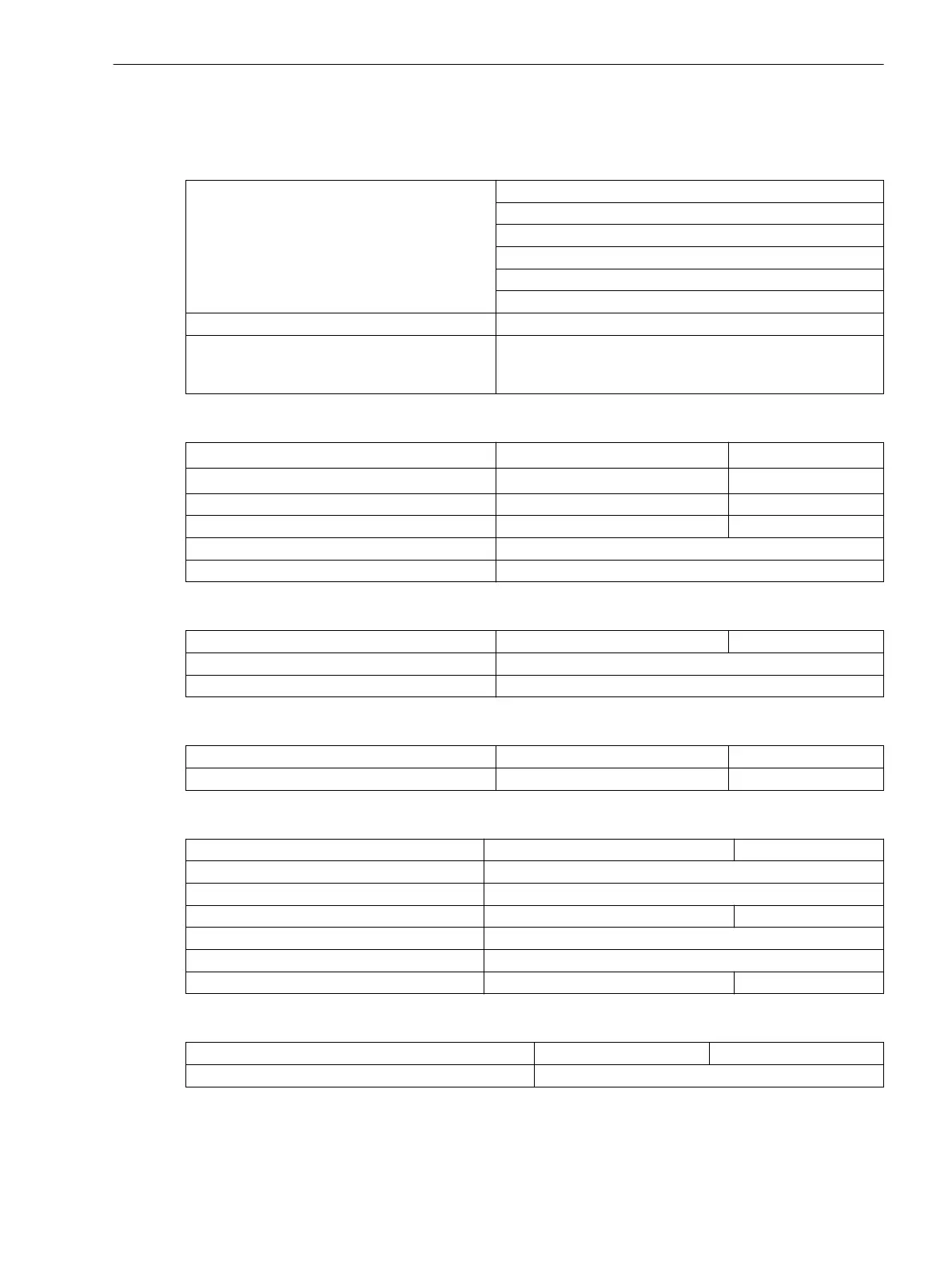
Paralleling Functions
Operating Modes
Synchrocheck Synchronism check
dead-line / live-bus
dead-bus / live-line
dead bus and dead line
bypassing
or combination of the above
Switching Synchronous Systems Switching at frequence equal
Switching Asynchronous Systems Closing the circuit breaker under asynchronous power
conditions taking into consideration the circuit breaker
operating time
Voltages
Maximum operating voltage U
max
20 V to 140 V Increments 1 V
Minimum operating voltage U
min
20 V to 125 V Increments 1 V
U1, U2 (U<, for de-energization) 1 V to 60 V Increments 1 V
U1, U2 (U>, for live-line) 20 V to 140 V Increments 1 V
Tolerances 1 % of pickup value or 0.5 V
Drop-off to pick-up ratio approx. 0.9 (U>) bzw. 1.1 (U<)
ΔU-Measurement
Voltage difference ΔU
0.0 V to 40.0 V Increments 0.1 V
Tolerances max. 0.5 V; typical 0.2 V
Drop-off to pick-up ratio approx. 1.05
Matching
Angle Correction of the Vector group
0° to 359° Increments 1°
Matching of the voltage transformers U1/U2 0.50 to 2.00 Increments 0.01
Synchronous Power Conditions
Δα-measurement
2° to 80° Increments 1°
Tolerances 0.5° at nominal frequency and small frequency difference
Dropout difference of the phase values 1°
Δf-measurement 0.00 Hz to 2.00 Hz Increments 0.01 Hz
Tolerances 10 mHz
Dropout Value Frequency 20 mHz
Release delay 0.00 s to 60.00 s Increments 0.01 s
Asynchronous Power Conditions
Δf-measurement
0.00 Hz to 2.00 Hz Increments 0.01 Hz
Tolerances 10 mHz
4.2
Technical Data
4.2 Paralleling Functions
SIPROTEC 4, 7VE61 and 7VE63, Manual 203
C53000-G1176-C163-3, Edition 10.2017

 Loading...


