Overvoltage Protection
Overvoltage protection serves to protect the electrical machine and connected electrical plant components
from the effects of inadmissible voltage increases. Overvoltages can be caused by incorrect manual operation
of the excitation system, faulty operation of the automatic voltage regulator, (full) load shedding of a gener-
ator, separation of the generator from the system or during island operation.
Functional Description
The overvoltage protection monitors one of the 6 voltage inputs of the device 7VE61 and 7VE63. A phase-
tophase voltage is usually connected. In case of a high overvoltage, tripping switchoff is performed with a
shorttime delay, whereas in case of less severe overvoltages, the switchoff is performed with a longer time
delay. Voltage thresholds and time delays can be set individually for both elements.
Each stage can be blocked individually and/or for both stages can be blocked, via binary input(s).
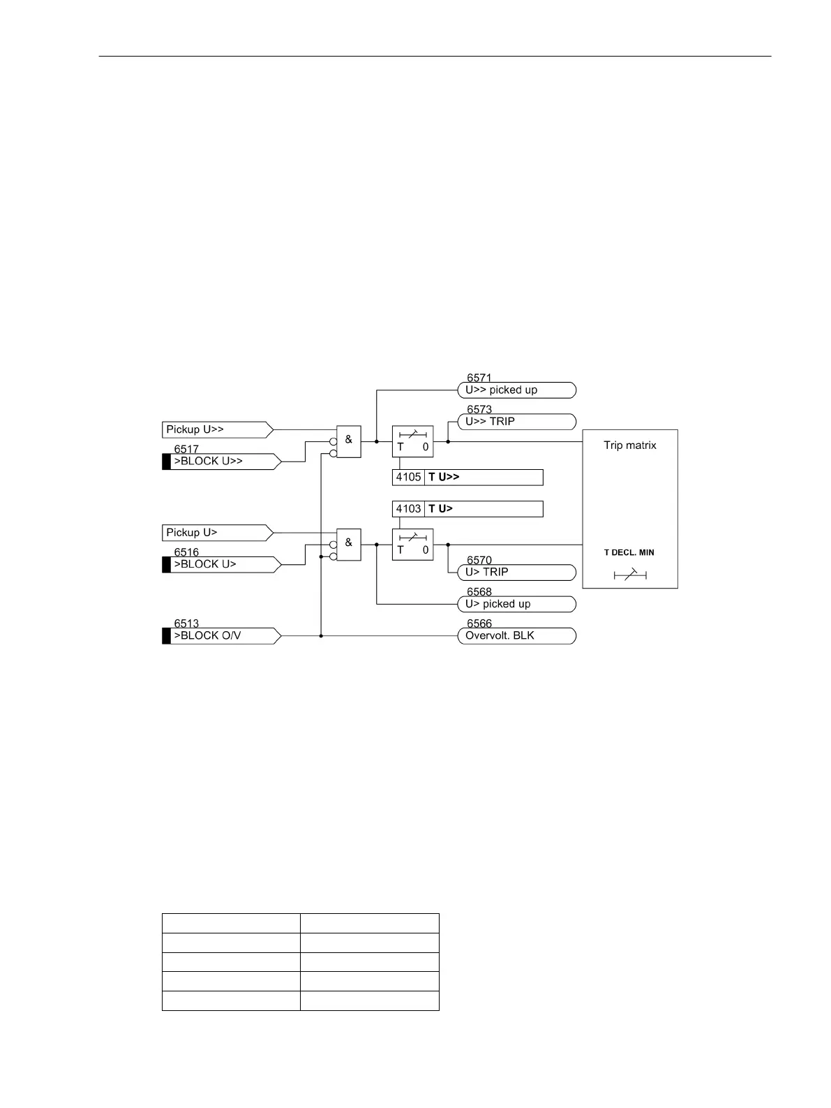
The following figure shows the logic diagram for the overvoltage protection function.
[logikdiagramm-des-ueberspannungsschutzes-020827-ho, 1, en_GB]
Figure 2-41 Logic Diagram of the Overvoltage Protection
Setting Notes
General
Overvoltage protection is only effective and available if this function was set during protective function config-
uration (Section 2.1.3 Functional Scope, address 141) OVERVOLTAGE is set to Enabled. If the function is not
required Disabled is set. Address 4101 OVERVOLTAGE serves to switch the function ON or OFF or to block
only the trip command (Block relay).
Setting Values
Using the parameter MEAS. INPUT one of the 6 voltage inputs (Ua to Uf) is allocated to the overvoltage
protection. The following allocation applies between voltage input and device connections:
Voltage input
Device connections
Ua Q1, Q2
Ub Q3, Q4
Uc Q5, Q6
Ud Q7, Q8
2.5
2.5.1
2.5.2
Functions
2.5 Overvoltage Protection
SIPROTEC 4, 7VE61 and 7VE63, Manual 85
C53000-G1176-C163-3, Edition 10.2017

 Loading...


