7VE63 approx. 12 VA approx. 25 VA
Bridging time for failure/short circuit (not in energized oper-
ation)
≥ 200 ms
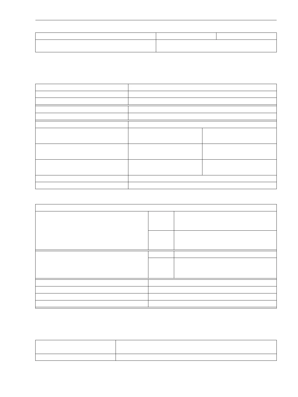
Binary Inputs and Outputs
Binary Inputs
Variant Quantity
7VE61**– 6 (configurable)
7VE63**– 14 (configurable)
Rated Voltage Range DC 24 V to 250 V, bipolar
Current Consumption, Energized approx. 1.8 mA, independent of control voltage
Secured Switching Threshold Changeable via jumpers
For nominal voltages DC 24 V/48 V/60 V/110 V/125 V U
high
≥ DC 19 V
U
low
≤ DC 10 V
For nominal voltages DC 110 V/125 V/220 V/250 V
and AC 115 V/230 V
U
high
≥ DC 88 V
U
low
≤ DC 44 V
For nominal voltages DC 220 V/250 V U
high
≥ DC 176 V
U
low
≤ DC 88 V
Maximum admissible voltage DC 300 V
Impulse filter on input 220 nF coupling capacity at 220 V with recovery time > 60 ms
Binary Outputs
Signalling / Command Relay
Number: 7VE61**– 9 (1 NO contact each, 1 of them optionally as NC
contacts) + 1 life contact
(NC or NO contact, selectable)
7VE63**– 17 (1 NO contact each, 2 of them optionally as NC
contacts) + 1 life contact
(NC or NO contact, selectable)
Switching capability CLOSE 1000 W/VA
BREAK 30 VA
40 W resistive
25 W at L/R ≤ 50 ms
Switching voltage 250 V
adm. current per contact (continuous) 5 A
adm. current per contact (close and hold) 30 A for 0.5 s (NO contact)
admissible total current on common path contacts 5 A continuous 30 A ≤ 0.5 s
Communication Interfaces
Operator Interface
Connection
Front side, non-isolated, RS232,
9-pin D-subminiature female connector for connection of a PC
Operation With DIGSI
4.1.3
4.1.4
Technical Data
4.1 General
SIPROTEC 4, 7VE61 and 7VE63, Manual 195
C53000-G1176-C163-3, Edition 10.2017

 Loading...


