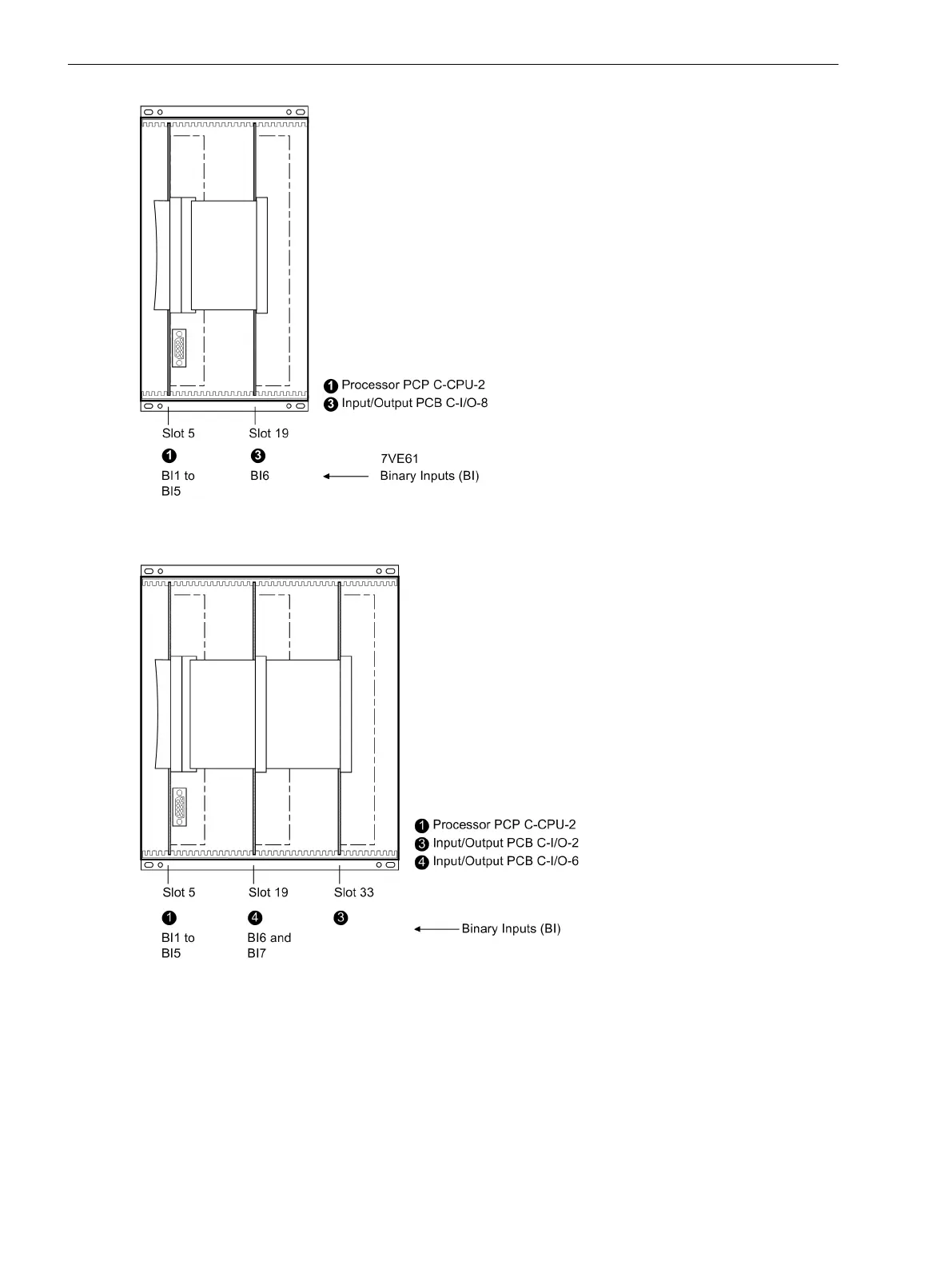
[frontansicht-geh-drittel-o-frontkappe7ve61-170203-oz, 1, en_GB]
Figure 3-2
Front view with housing size
1
/
3
after removal of the front cover (simplified and scaled down)
[frontansicht-7um621-020829-ho, 1, en_GB]
Figure 3-3
Front view with housing size
1
/
2
after removal of the front cover (simplified and scaled down)
Switching Elements on the Printed Circuit Boards
Processor Printed Circuit Board C–CPU–2
The layout of the printed circuit board for the C-CPU-2 board is illustrated in the following figure. The location
and ratings of the miniature fuse (F1) and of the buffer battery (G1) are shown in the following figure.
3.1.2.3
Mounting and Commissioning
3.1 Mounting and Connections
148 SIPROTEC 4, 7VE61 and 7VE63, Manual
C53000-G1176-C163-3, Edition 10.2017

 Loading...


