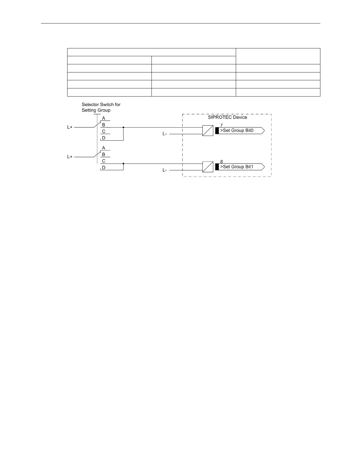
Table 3-1 Changing setting groups using binary inputs
Binary Input Active Group
>Param.Wahl1 >Param. Wahl2
no no Group A
yes no Group B
no yes Group C
yes yes Group D
[einstellgruppenumschaltung-ueber-binaere-160502-wlk, 1, en_GB]
Figure 3-1 Connection diagram (example) for setting group switching using binary inputs
Hardware Modifications
General
General
A subsequent adaptation of the hardware to the power system conditions can, for example, become necessary
with regard to the control voltage for binary inputs or the termination of bus-capable interfaces. Follow the
procedure described in this section, whenever hardware modifications are done.
Auxiliary Voltage
There are different power supply voltage ranges for the auxiliary voltage (refer to the Ordering Information in
the Appendix). The variants for DC 60 V/110v/125 V and DC 110 V/125 V/220 V, AC 115/230 V are inter-
changeable by modifying the position of the jumpers. Jumper setting allocation for the rated voltage ranges,
and their location on the PCB are described in this Section under the margin title “Processor Board C-CPU-2”.
Location and ratings of the miniature fuse and the buffer battery are also given.
When the device is delivered, these jumpers are set according to the name-plate sticker, and they do not need
to be altered.
Live Status Contact
The life status contact of the device is a changeover contact from which either the NC contact or the NO
contact can be connected to the device terminals via a plug-in jumper (X40). Assignments of the jumpers to
the contact type and the spatial layout of the jumpers are described in the following Section at margin
heading “Processor Board C-CPU-2”.
Control Voltage for Binary Inputs
When the device is delivered the binary inputs are set to operate with a voltage that corresponds to the rated
voltage of the power supply. If the rated values differ from the power system control voltage, it may be neces-
sary to change the switching threshold of the binary inputs.
To change the switching threshold of a binary input, one jumper must be changed for each input. The alloca-
tion of the plug-in jumpers to the binary inputs and their actual positioning are described in this Section.
3.1.2
3.1.2.1
Mounting and Commissioning
3.1 Mounting and Connections
SIPROTEC 4, 7VE61 and 7VE63, Manual 145
C53000-G1176-C163-3, Edition 10.2017

 Loading...


