It is possible to convert the R485 interface to a RS232 interface by changing the jumper positions and vice-
versa.
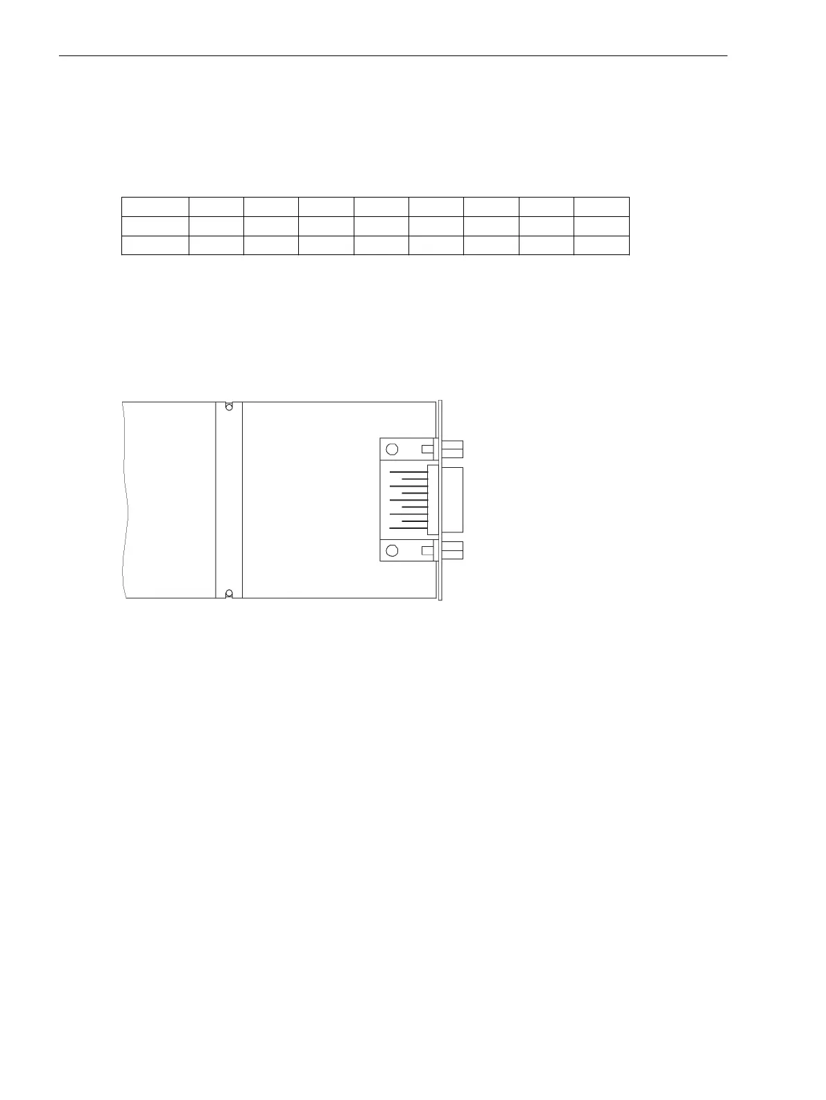
The jumper positions for the alternatives RS232 or RS485 (as in Figure 3-9) are derived from the following
table.
Table 3-15 Configuration for RS232 or RS485 on the interface module
Jumper X5 X6 X7 X8 X10 X11 X12 X13
RS232 1-2 1-2 1-2 1-2 1-2 2-3 1-2 1-2
RS485 2-3 2-3 2-3 2-3 2-3 2-3 1-2 1-2
The jumpers X5 to X10 must be plugged in the same way!
The jumpers are preset at the factory according to the configuration ordered.
Analog Output
The AN20 analog output interface module (see Figure 3-11) has 2 floating channels with a current range of 0
to 20 mA (unipolar, max. 350 Ω).
The location on the C–CPU–2 board is “B” and/or “D” depending on the variant ordered (see Figure 3-8).
[analogausgabe-an20-240702-kn, 1, en_GB]
Figure 3-11 AN20 analog output interface board
Reassembly
The device is assembled in the following steps:
•
Insert the boards carefully in the housing. The mounting locations of the modules are shown in
Figure 3-3 and . For the surface mounting device variant, it is recommended to press the metal lever of
the module when inserting the C-CPU-2 processor board. This eases plug connector insertion.
•
Plug in the plug connectors of the ribbon cable onto the input/output modules I/O and then onto the
processor module C-CPU-2. Be careful not to bend any connector pins! Do not apply force!
•
Connect the plug connectors of the ribbon cable between the C-CPU-2 board and the front panel to the
front panel plug connector.
•
Press the plug connector interlocks together.
•
Replace the front panel and screw it tightly to the housing.
•
Replace the covers again.
•
Screw the interfaces on the rear panel of the device tight again.
This activity does not apply if the device is for surface mounting.
3.1.2.5
Mounting and Commissioning
3.1 Mounting and Connections
158 SIPROTEC 4, 7VE61 and 7VE63, Manual
C53000-G1176-C163-3, Edition 10.2017

 Loading...


