[prozessorbaugruppe_c_cpu_2_020829_ho, 1, en_GB]
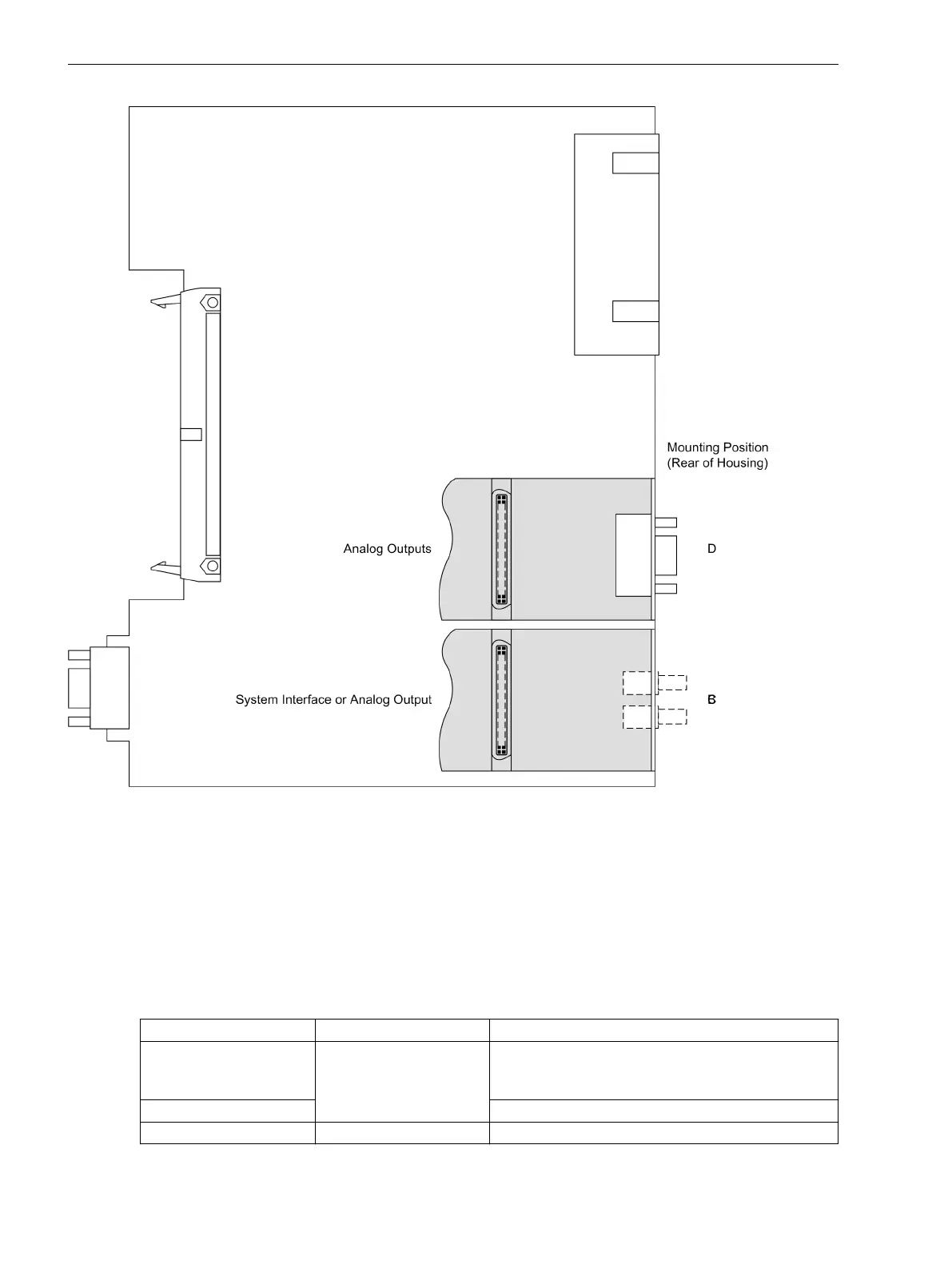
Figure 3-8
Processor printed circuit board C–CPU-2 with interface modules
Please note the following:
•
The interface modules can only be replaced in devices for panel flush mounting and cubicle mounting.
Devices in surface mounting housings with double-level terminals can be changed only in our manufac-
turing centre.
•
Only interface modules can be used with which the device can be ordered from the factory also in
accordance with the order number, see also Appendix A Ordering Information and Accessories.
Table 3-14
Replacing interface modules
Interface Mounting Location / Port Replacement Module
System Interface
B
Only interface modules that can be ordered in our
facilities via the order key (see Appendix A Ordering
Information and Accessories)
Analog Output 2 x 0 to 20 mA or 4 to 20 mA
Analog Output D 2 x 0 to 20 mA or 4 to 20 mA
Mounting and Commissioning
3.1 Mounting and Connections
156 SIPROTEC 4, 7VE61 and 7VE63, Manual
C53000-G1176-C163-3, Edition 10.2017

 Loading...


