The order numbers of the replacement modules can be found in the Appendix in Section A Ordering Informa-
tion and Accessories.
EN100 Ethernet Module (IEC 61850)
The Ethernet interface module has no jumpers. No hardware modifications are required to use it.
Termination
For bus-capable interfaces a termination is necessary at the bus for each last device, i.e. terminating resistors
must be connected. With the 7VE61 and 7VE63 device, this concerns the variants with RS485 or PROFIBUS
interfaces.
The terminating resistors are located on the RS485 or Profibus interface module, which is on the C–CPU–2
board ((1) in Figure 3-2 and Figure 3-3), or directly on the PCB of the C-CPU-2 board (see margin title “C-CPU-2
Processor Board”, Table 3-7).
Figure 3-8 shows the PCB of the C-CPU-2 with the layout of the boards.
The module for the RS485 interface is shown in Figure 3-9, the module for the Profibus interface in
Figure 3-10.
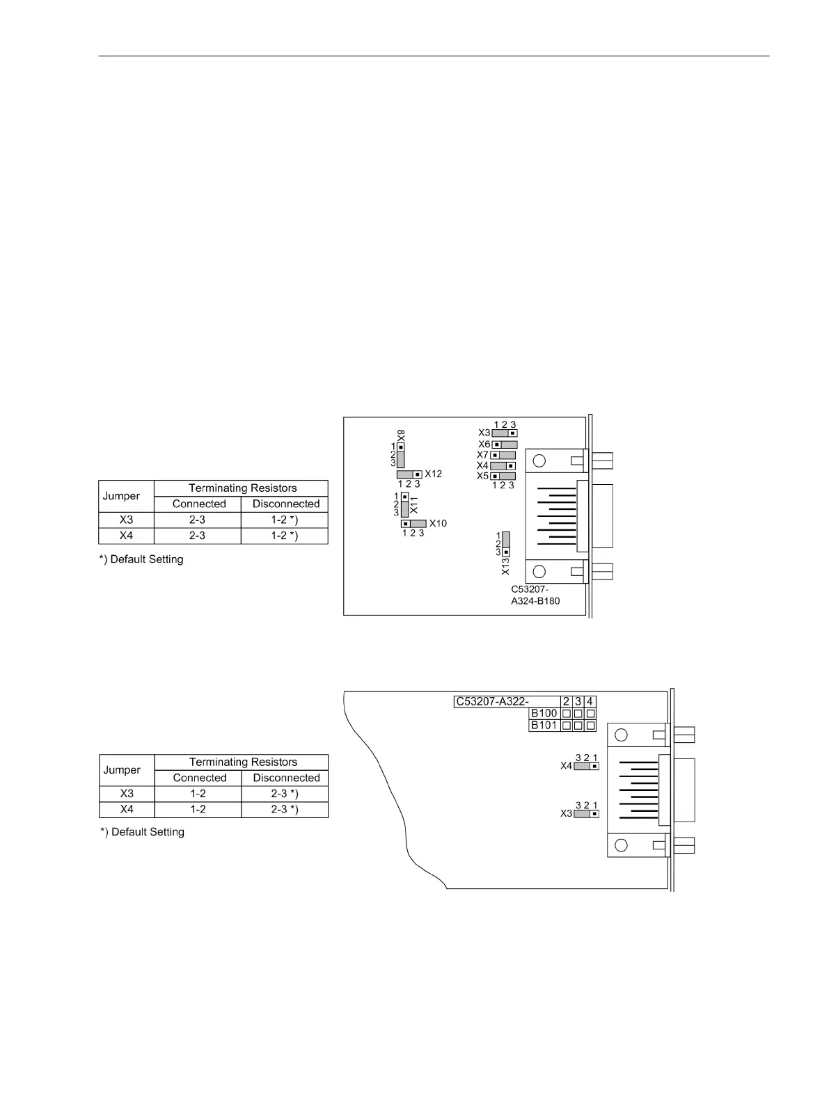
On delivery the jumpers are set so that the terminating resistor are disconnected. Both jumpers of a module
must always be plugged in the same way.
[steckbruecken-rs485-020313-kn, 1, en_GB]
Figure 3-9 Position of terminating resistors and the plug-in jumpers for configuration of the RS485 inter-
face
[steckbruecken-profibus-020313-kn, 1, en_GB]
Figure 3-10 Position of the plug-in jumpers for the configuration of the terminating resistors at the
Profibus (FMS and DP), DNP 3.0 and Modbus interfaces
The terminating resistors can also be connected externally (e.g. to the terminal block), see Figure 3-5. In this
case, the matching resistors located on the RS485 or PROFIBUS interface module or directly on the PCB of the
C-CPU-2 board of must be disabled.
Mounting and Commissioning
3.1 Mounting and Connections
SIPROTEC 4, 7VE61 and 7VE63, Manual 157
C53000-G1176-C163-3, Edition 10.2017

 Loading...


