Table 3-7 Jumper setting of the Terminating Resistors of Interface RS485 on the C-CPU-2 processor
board
Jumper Terminating Resistor enabled Terminating resistor disabled Presetting
X103 2-3 1-2 1-2
X104 2-3 1-2 1-2
NOTE
Both jumpers must always be plugged in the same way !
Jumper X90 has currently no function. The factory setting is 1-2.
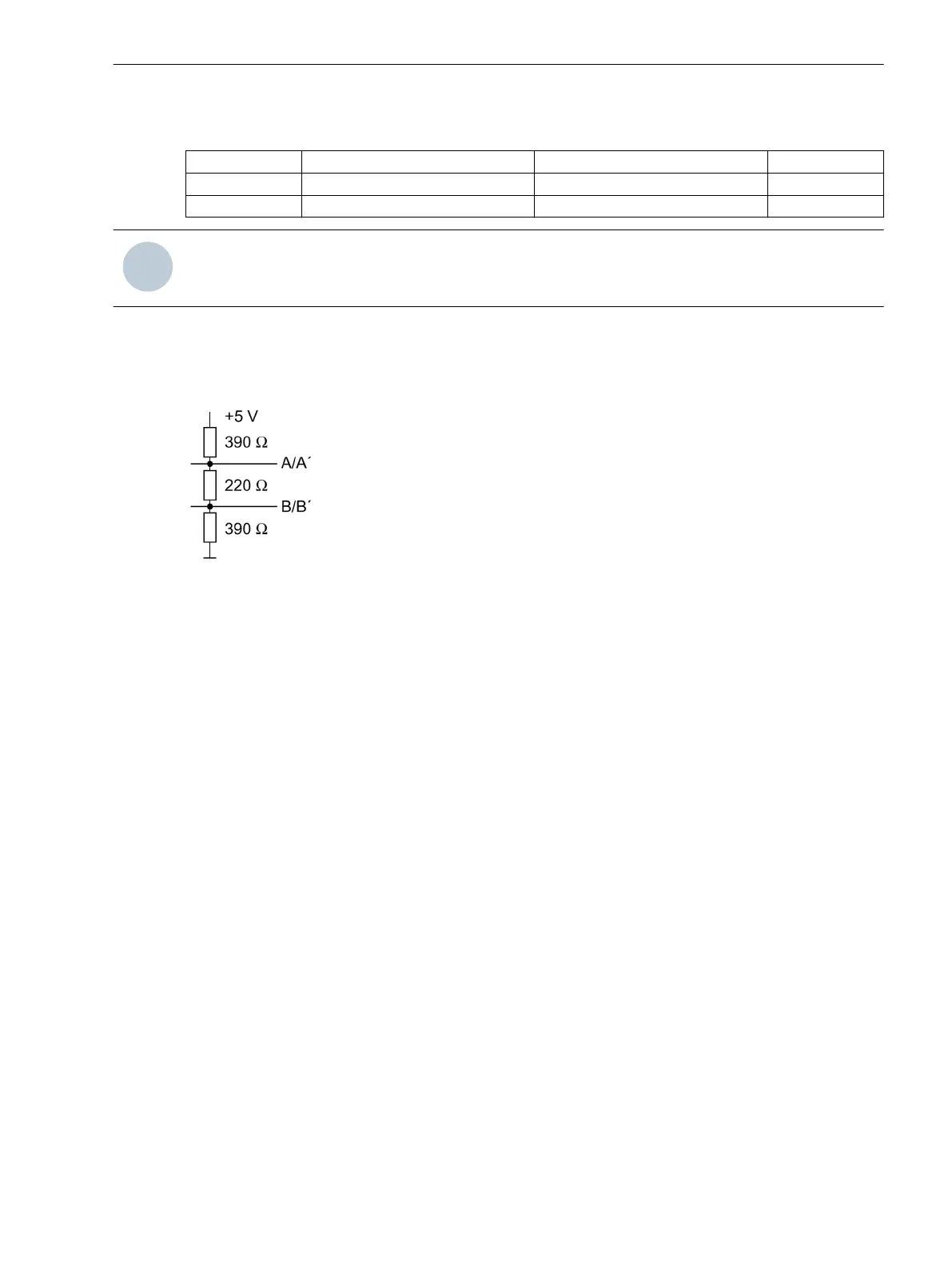
The terminating resistors can also be connected externally (e.g. to the connection module). In this case, the
terminating resistors located on the RS485 or PROFIBUS interface module or directly on the PCB of the
processor board C-CPU-2 must be de-energized.
[externe-terminierung-020313-kn, 1, en_GB]
Figure 3-5 Termination of the RS485 interface (external)
Mounting and Commissioning
3.1 Mounting and Connections
SIPROTEC 4, 7VE61 and 7VE63, Manual 151
C53000-G1176-C163-3, Edition 10.2017

 Loading...


