Input/Output Board C–I/O-1
[ein-ausgabebgr-c-io-1-160502-wlk, 1, en_GB]
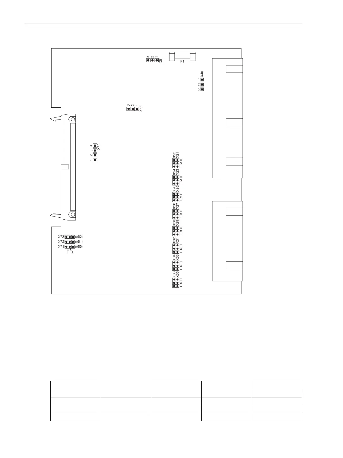
Figure 3-6
Input/output board C-I/O-1 with representation of the jumper settings required for the board
configuration
The selected control voltages of binary inputs BI7 to BI14 are checked according to Table 3-8. Jumper settings
for the contact mode of binary output BO10 are checked according to Table 3-9.
Figure 3-3 illustrates the assignment of the binary inputs to the mounting location.
Pickup voltages of BI7 to BI14
Table 3-8
Jumper settings for pickup voltages (DC voltage) of the binary inputs BI7 and BI14 on the C–
I/O-1 board
Binary Inputs Binary Inputs
19 V Threshold
1)
88 V Threshold
3)
176 V Threshold
3)
BI7 X21/X22 L M H
BI8 X23/X24 L M H
BI9 X25/X26 L M H
BI10 X27/X28 L M H
Mounting and Commissioning
3.1 Mounting and Connections
152 SIPROTEC 4, 7VE61 and 7VE63, Manual
C53000-G1176-C163-3, Edition 10.2017

 Loading...


