[logik-schalten-synchr-netze-110403-kn, 1, en_GB]
Figure 2-14
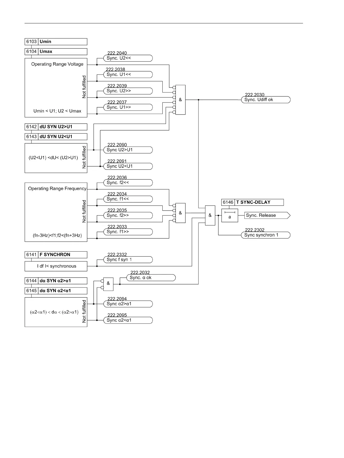
Logic diagram: Switching synchronous systems (illustration for channel 1)
Switching Asynchronous Systems
This state occurs with the power system and generator (open generator circuit breaker). Here the conditions
voltage difference ΔU and frequency difference Δf are checked, and taking into consideration the angle differ-
ence and the operating time of the circuit breaker, the closure command time is calculated so that the voltage
vectors are identical at the instant the circuit breaker poles (ΔU ≈ 0, Δα ≈ 0) make contact.
The generator can be automatically brought to synchronism conditions by the balancing commands for
voltage and frequency (see below).
Enabling for closure is issued if the conditions are fulfilled, according to the logic diagram in Figure 2-15. The
close command is issued at a time before synchronization corresponding to the operating time of the circuit
2.2.1.10
Functions
2.2 Paralleling Functions
50 SIPROTEC 4, 7VE61 and 7VE63, Manual
C53000-G1176-C163-3, Edition 10.2017

 Loading...


