PAUSE. If the parameter 6182 T U PULS MAX is set to ∞ there is no time restriction and a continuous pulse is
output until the calculated time has expired.
In particular with hydro-electric power stations, generator rotation speed can be subject to fluctuations.
Actuator commands established from a current frequency value could thus be incorrect. The option is there-
fore provided using the parameter 6186 SMOOTHING f of subjecting the frequency difference to an aver-
aging with different smoothing factors 1 to 10.
If the frequency difference is Δf ≈ 0 i.e. the generator runs in synchronism with the power system but the
connection conditions are not yet fulfilled, synchronization would not be possible or would take a very long
time. In such cases a “kick impulse” can be issued if the parameter 6187 KICK PULSE = ON was selected and
kick impulses thus enabled. These are issued only if the duration until synchronism exceeds an adjustable time
set by parameters 6189 T SW-ON MIN. This insures that kick impulses are not issued immediately before
synchronism is achieved, but only if the voltage vectors are not coinciding in the immediate future. For the set
value of the parameter 6189 applies the formula: T SW-ON MIN ≈ 1/(2·Δf). The highest of the both set values
of the parameter 6132 df ASYN f2>f1 and 6133 df ASYN f2<f1 are selected for Δf.
The kick impulse is initiated in the direction of the parameter setting from Δf KICK (according to the positive
or negative signs of the frequency value). Its length is calculated from the frequency change df2/dt and the set
value of the parameter 6188 Δf KICK.
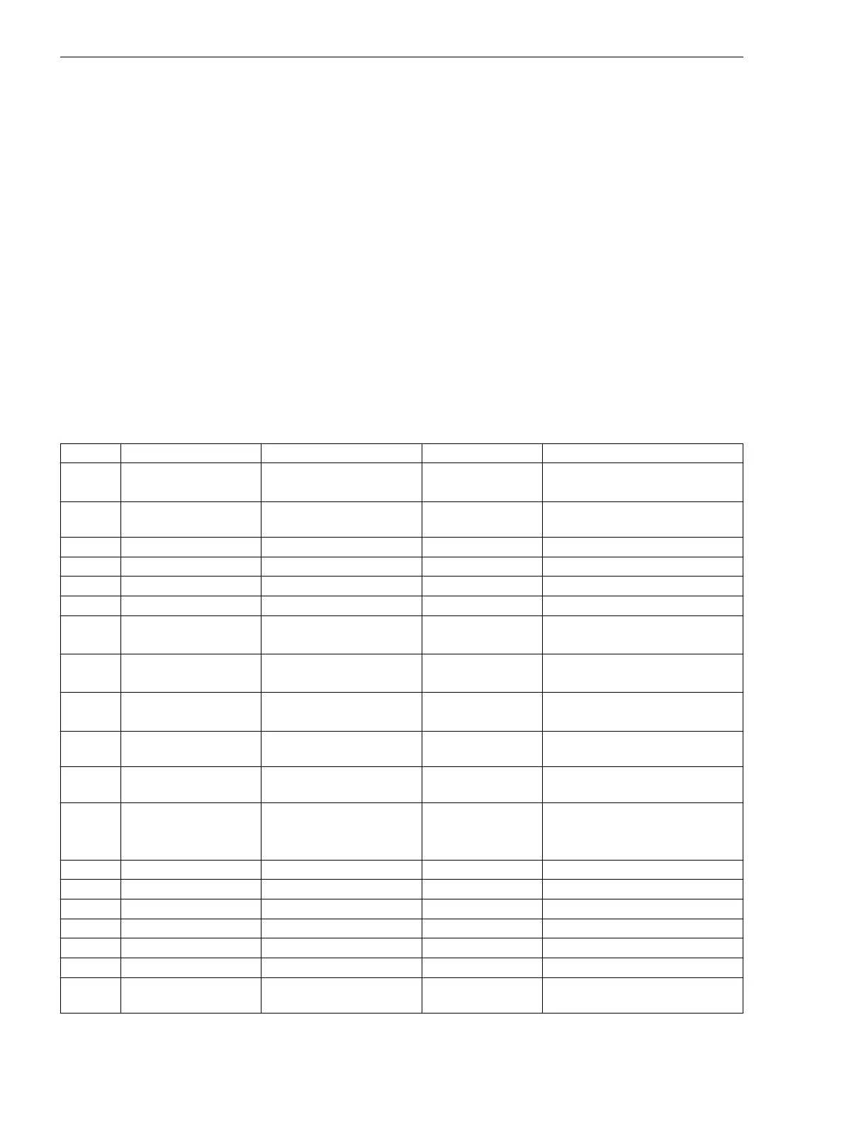
Settings
Addresses which have an appended “A” can only be changed with DIGSI, under “Additional Settings”.
Addr. Parameter Setting Options Default Setting Comments
6101 Synchronizing ON
OFF
OFF Synchronizing Function
6102 SyncSD (Einstellmöglichkeiten
anwendungsabhängig)
none synchronizable switching device
6103 Umin 20 .. 125 V 90 V Minimum voltage limit: Umin
6104 Umax 20 .. 140 V 110 V Maximum voltage limit: Umax
6105 U< 1 .. 60 V 5 V Threshold U1, U2 without voltage
6106 U> 20 .. 140 V 80 V Threshold U1, U2 with voltage
6107 SYNC U1<U2> YES
NO
NO ON-Command at U1< and U2>
6108 SYNC U1>U2< YES
NO
NO ON-Command at U1> and U2<
6109 SYNC U1<U2< YES
NO
NO ON-Command at U1< and U2<
6111A TSUP VOLTAGE 0.0 .. 60.0 sec 0.1 sec Supervision time Dead Line / Dead
Bus
6112 T-SYN. DURATION 0.01 .. 1200.00 sec 1200.00 sec Maximum duration of
synchronism-check
6113 PHASE SEQUENCE NO
L1 L2 L3
L1 L3 L2
NO Phase sequence check
6120 T-CB close 10 .. 1000 ms 2147483647 ms Closing (operating) time of CB
6121 Balancing U1/U2 0.50 .. 2.00 1.00 Balancing factor U1/U2
6122A ANGLE ADJUSTM. 0 .. 359 ° 0 ° Angle adjustment (transformer)
6124 VT Un1, primary 0.10 .. 999.99 kV 15.75 kV VT nominal voltage U1, primary
6125 VT Un2, primary 0.10 .. 999.99 kV 15.75 kV VT nominal voltage U2, primary
6126 Unom SECONDARY 80 .. 125 V 100 V Rated Secondary Voltage (Ph-Ph)
6127 T CLS CMD MIN 0.01 .. 10.00 sec 0.10 sec Min close command time of the
CB
2.2.2.2
Functions
2.2 Paralleling Functions
76 SIPROTEC 4, 7VE61 and 7VE63, Manual
C53000-G1176-C163-3, Edition 10.2017

 Loading...


