center value is not used as for voltage balancing commands, but established by the parameter 6185 Δf SET
POINT (see Figure 2-39). Since it is preferred to parallel generators in over-synchronism following conditions
should be imposed:
Δf SET POINT < 0.5 · df ASYN f2>f1
With f2 > f1 a positive sign results.
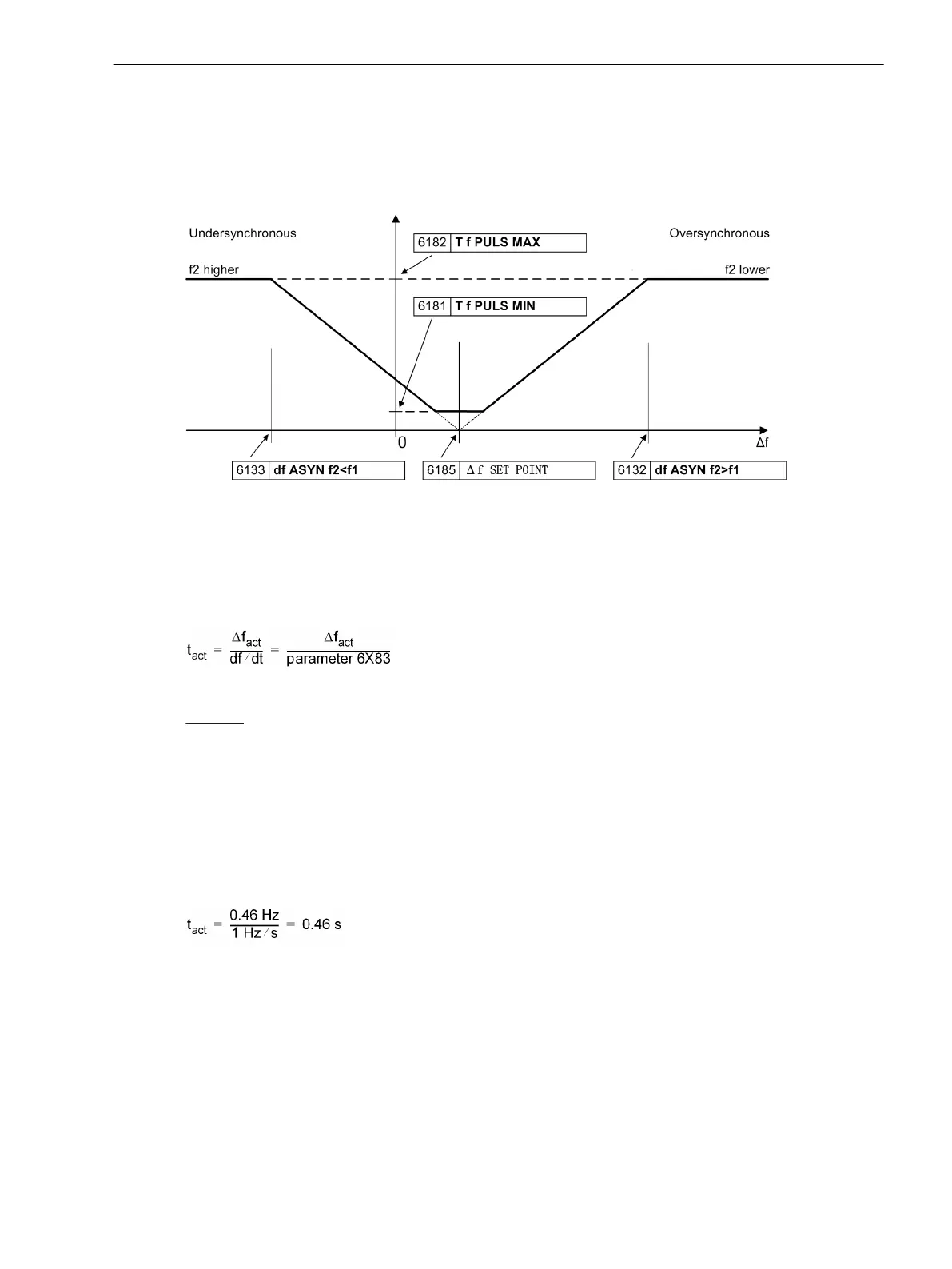
[ve6-frequenzverstellbereich-190303-kn, 1, en_GB]
Figure 2-39 Determining frequency balancing pulses
The parameter 6181 T f PULS MIN establishes the duration of the minimum actuator pulse, with parameter
6182 T f PULS MAX that of the maximum actuator pulse.
The parameter 6183 df2 / dt informs the device of the rate of change of the controller. The following
formula results from this:
[ve6-stellimpulse-frequenz-gleichung-170303-kn, 1, en_GB]
Example:
Setting value 6132
df ASYN f2>f1 = 0.1 Hz
Setting value 6183 df2 / dt = 1 Hz/s
Setting value 6185 Δf SET POINT = 0.04 Hz
actually measured df = +0.5 Hz
These setting values and the measure value result in the following actuator time:
Δf SET POINT = 0.5 · 0.1 Hz = + 0.05 Hz
Δfact = I df – Δf SET POINT I = I +0.5 Hz – 0.04 Hz I = 0.46 Hz
[ve6-stellimpulse-frequenz-beispiel-170403-kn, 1, en_GB]
The minimum actuator pulse is set by the reaction of the controller or of the entire system and is to be estab-
lished on commissioning.
The maximum actuator time is intended to avoid excessive overshoot on large Δf. The appropriate setting
value is to be established on commissioning.
Depending on the sign i.e. whether f2 is smaller or larger than f1, the actuator direction (“higher” or “lower” is
established. In the example “lower” pulses are output. The resulting times are checked against the parameters
for minimum (6181) and maximum (6182) pulse time. If the calculated time for the actuator pulse is less than
the minimum pulse time, a pulse with minimum pulse time is output. If the time for the actuator pulse is
greater than the maximum pulse time, the actuator pulse is limited to the maximum pulse time. For this the
long actuator pulse is divided into multiple shorter pulses, which are interrupted by the pause time 6184 T f
Functions
2.2 Paralleling Functions
SIPROTEC 4, 7VE61 and 7VE63, Manual 75
C53000-G1176-C163-3, Edition 10.2017

 Loading...


