long actuator pulse is divided into multiple shorter pulses, which are interrupted by the pause time 6174 T U
PAUSE. Using the numerical values of the example and a setting of the parameter 6172 T U PULS MAX = 1 s
a division on two one second pulses resulted. If the parameter 6172 T U PULS MAX is set to ∞ there is no
time restriction and a continuous pulse is output until the calculated time has expired.
In case of very unsettled power system conditions it may be advantageous to filter the measured values. With
parameter 6175 SMOOTHING U, which is only accessible under DIGSI, a smoothing mean value formation can
be selected with the stages 1 (weak smoothing) to 10 (strong smoothing). Normally, the default setting (1) is
sufficient. With setting 0 no smoothing is required.
Overexcitation Limitation
In combination with the frequency adjustment the overexcitation (U/f) is continually monitored. In case of
exceeding parameter 6176 (U/Un) / (f/fn), which is accessible under DIGSI, the target voltage for the
voltage adjustment of side 2 (U2) is reduced or limited to the maximum permissible value. The voltage adjust-
ment value is derived from the limitation of ΔU
adjust
= U
2,max
- U
2
.
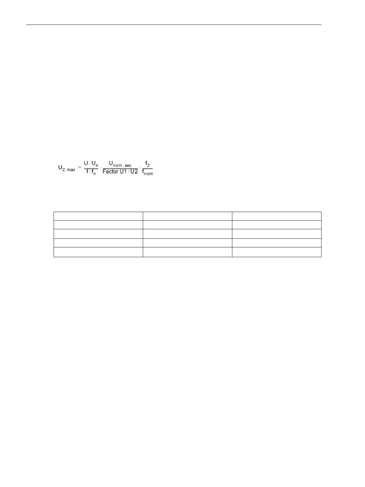
The maximum permissible secondary voltage U
2,max
can be
[uebererregungsbegrenz-u2max, 1, en_GB]
derived from the relation.
For an estimation of U
2,max
the following example applies the factory settings (see table).
Address
Parameter Default Setting
6176
(U/Un) / (f/fn)
1.1
6126 U
Nenn,sek
100 V
6121
Balancing U1/U2
1
270 f
Nom
z.B. 50 Hz
If, for example, at the moment of synchronization, the generator frequency f
2
= 50.05 Hz, then the following
applies: f2/f
Nom
= 50.05 Hz/50 Hz = 1.001. The limit of the maximum permissible generator voltage U
2,max
is
110.11 V as secondary voltage. The voltage adjustment commands are performed in such manner that such
voltage is not exceeded. If the voltage is U2 > U
2,max
, adjustment commands are performed to reduce U2 until
meeting the condition again.
Usually, the preset parameter 6176 (U/Un) / (f/fn) = 1.10 does not need to be changed. If a change is
implemented, it should be noted that monitoring applies to secondary values exclusively. If the generator
voltage and the primary transformer voltage differ from each other, such deviation should be taken into
consideration in parameter at address 6176.
Setting example: The following are default settings:
U
N,G
= 6,3 kV
U
N,Transformer. prim
= 6 kV
U
N,Transformer sek
= 100 V
U/f = 1,1
The overexcitation limit shall be calculated as follows:
Parameter 6176 (U/Un) / (f/fn) = U / f * U
N,G
/ U
N,Transformer prim
= 1.1 (6,3 kV / 6 kV) = 1.1 * 1.05 = 1.15.
Together with the factory settings and considering that f
2
= f
Nom
, the maximum permissible voltage U
2,max
=
115 V.
Frequency Balancing Pulses
With the parameters 6132 df ASYN f2>f1 and 6133 df ASYN f2<f1 for asynchronous parallel switching
a range is set up for the admissible frequency difference. As a target value for at the actuator commands, the
Functions
2.2 Paralleling Functions
74 SIPROTEC 4, 7VE61 and 7VE63, Manual
C53000-G1176-C163-3, Edition 10.2017

 Loading...


