Note:
•
In case of an termination of the communication link between transmitter and receiver, the value of the
transformer tap is marked “invalid” and a running synchronization is terminated. Tracking of the
external transformer tap is not possible!
•
An invalid transformer tap setting is transmitted by GOOSE as “63”. This is detected by 7VE632x, which
marks all measured values as “invalid”.
•
In accordance with IEC 61850, the transformer taps only transmit integers. The transmission of intervals
is thus not possible.
Frequency and Voltage Balancing
Balancing commands can be output only by the device variants 7VE6***-*****-*C or D. This functionality
can be also used if at least one of the parameters 6170 U BALANCING and 6180 f BALANCING in contrast to
the delivery setting is not set to OFF, but one of the alternatives offered is selected. For actuator pulses to a
voltage controller U BALANCING = Pulse is selected for control of a transformer tap switch = Tap changer.
For adaptation of the balancing commands to the characteristic of the voltage controller, in addresses 6171 to
6174 the actuator, the pause times and the rate of voltage change are set.
Voltage Balancing Pulses
With the parameters 6130 dU ASYN U2>U1 and 6131 dU ASYN U2<U1 for a synchronous parallel connec-
tion a range is extended for the admissible voltage difference whose average value is adopted as a target
value for the balancing commands.
The parameter 6171 T U PULS MIN establishes the duration of the minimum actuator pulse, with parameter
6172 T U PULS MAX that of the maximum actuator pulse. The latter establishes also the duration of the
(constant) actuator pulses for the transformer tap switches.
The minimum actuator pulse is set by the reaction of the controller or of the entire system and is to be estab-
lished on commissioning.
The maximum actuator time is intended to avoid excessive overshoot on large ΔU. The appropriate setting
value is to be established on commissioning.
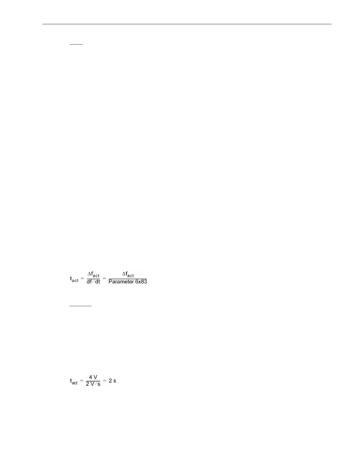
The parameter 6173 dU2 / dt informs the device of the rate of change of the controller. The following
formula results from this:
[ve6-stellimpulse-u-gleichung-170303-kn, 1, en_GB]
Example:
Setting value 6130
dU ASYN U2>U1 = 2 V
Setting value 6131dU ASYN U2<U1 = 2 V
Setting value 6173 dU2 / dt = 2 V/s
actually measured dU = –4 V
These setting values and the measure value result in the following actuator time:
ΔUact = I dU – 0.5 · (Parameter 6130 – Parameter 6131) I =
I –4 V–0,5 · (2 V – 2 V) I = 4 V
[ve6-stellimpulse-spannung-beispiel-170403-kn, 1, en_GB]
Depending on the sign i.e. whether U2 is smaller or larger than U1, the actuator direction (“higher” or “lower”)
is established. In the example “higher” pulses are output. The resulting times are checked against the parame-
ters for minimum (6171) and maximum (6172) pulse time. If the calculated time for the actuator pulse is less
than the minimum pulse time, a pulse with minimum pulse time is output. If the time for the actuator pulse is
greater than the maximum pulse time, the actuator pulse is limited to the maximum pulse time. For this the
Functions
2.2 Paralleling Functions
SIPROTEC 4, 7VE61 and 7VE63, Manual 73
C53000-G1176-C163-3, Edition 10.2017

 Loading...


