Time Synchronization Interface
Either DC 5 V, 12 V or 24 V time synchronization signals can be processed if the connections are made as indi-
cated in the table below.
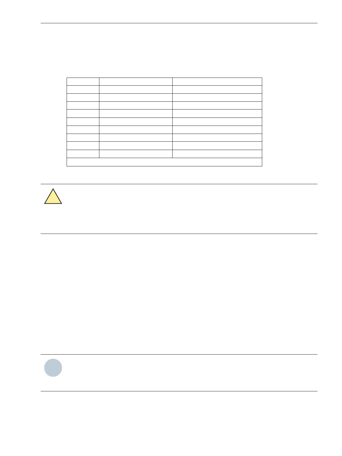
Table 3-18 D-subminiature connector assignment of the time synchronization interface
Pin-No. Description Signal Meaning
1 P24_TSIG Input 24 V
2 P5_TSIG Input 5 V
3 M_TSIG Return Line
4
–
1)
–
1)
5 SHIELD Shield Potential
6 – –
7 P12_TSIG Input 12 V
8
P_TSYNC
1)
Input 24 V
1)
9 SHIELD Shield Potential
1)
assigned, but not used
Fibre-optic Cables
WARNING
Laser rays!
²
Do not look directly into the fiber-optic elements!
Signals transmitted via optical fibers are unaffected by interference. The fibers guarantee electrical isolation
between the connections. Transmit and receive connections are represented by symbols.
The character idle state for the optical fibre interface is “Light off”. If the character idle state is to be changed,
use the operating program DIGSI, as described in the SIPROTEC 4 System Description.
Checking the Device Connections
General
By checking the device connections the correct installation of the protection device e.g. in the cubicle must be
tested and ensured. This includes wiring check and functionality as per drawings, visual assessment of the
protection system, and a simplified functional check of the protection device.
Auxiliary Power Supply
Before the device is connected for the first time to voltage, it should be have been at least 2 hours in its oper-
ating room, in order to attain temperature equilibrium and to avoid dampness and condensation.
NOTE
If a redundant supply is used, there must be a permanent, i.e. uninterruptible connection between the
minus polarity connectors of system 1 and system 2 of the DC voltage supply (no switching device, no
fuse), because otherwise there is a risk of voltage doubling in case of a double earth fault.
Switch on the auxiliary voltage circuit breaker (supply protection), check voltage polarity and amplitude at the
device terminals or at the connection modules.
3.2.2
Mounting and Commissioning
3.2 Checking Connections
SIPROTEC 4, 7VE61 and 7VE63, Manual 165
C53000-G1176-C163-3, Edition 10.2017

 Loading...


