•
CTS = Clear to send
•
GND = Signal/Chassis Ground
The cable shield is to be grounded at both ends. For extremely EMC-prone environments, the GND may be
connected via a separate individually shielded wire pair to improve immunity to interference.
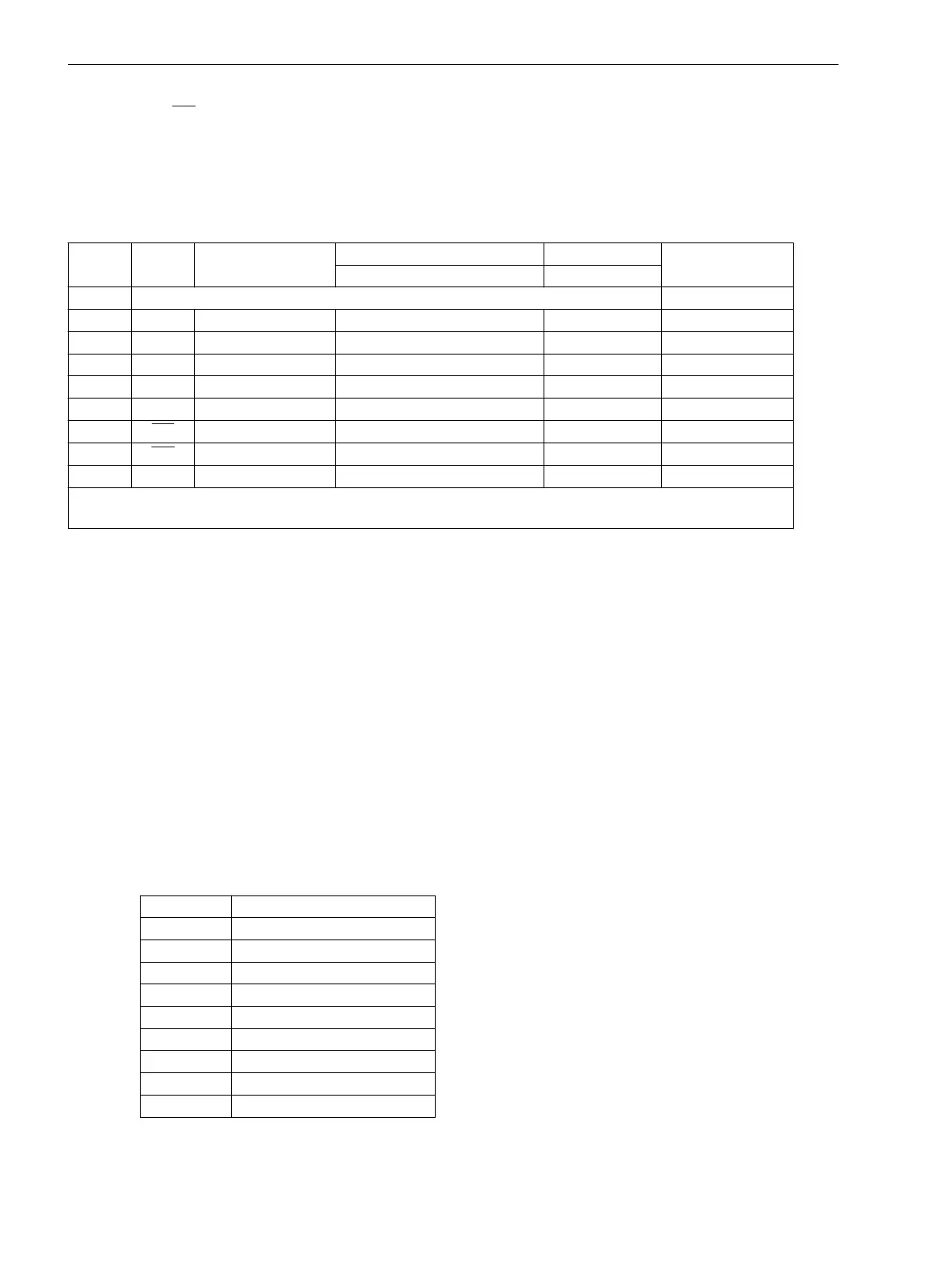
Table 3-16 Assignment of the connectors for the various serial interfaces
Pin-No. RS232 RS485 Profibus FMS Slave, RS485 Modbus RS485 EN 100 electr.
RJ45
Profibus DP Slave, RS485 DNP 3.0 RS485
1 Shield (with shield ends electrically connected) Tx+
2 RxD – – – Tx–
3 TxD A/A’ (RxD/TxD-N) B/B’ (RxD/TxD-P) A Rx+
4 – – CNTR-A (TTL) RTS (TTL level) –
5 GND C/C’ (GND) C/C’ (GND) GND1 –
6 – – +5 V (max. load <100 mA) VCC1 Rx–
7 RTS
–
1)
– – –
8 CTS B/B’ (RxD/TxD-P) A/A’ (RxD/TxD-N) B –
9 – – – – not available
1)
Pin 7 also carries the RTS signal with RS232 level when operated as RS485 Interface. Pin 7 must therefore not be
connected
Termination
The RS485 interface is capable of half-duplex operation with signals A/A' and B/B' with the common reference
potential C/C' (EARTH). Verify that only the last device on the bus has the terminating resistors connected, and
that the other devices on the bus do not. The jumpers for the terminating resistors are on the interface
module RS485 (see Figure 3-9) or on the Profibus RS485 (see Figure 3-10). or directly on the C–CPU–2 (see
Figure 3-4 and Table 3-7). The terminating resistors can also be connected externally (e.g. to the connection
module as illustrated in Figure 3-5). In this case, the terminating resistors located on the module must be disa-
bled.
If the bus is extended, make sure again that only the last device on the bus has the terminating resistors
enabled, and that all other devices on the bus do not.
Analog Output
The two analog values are output as currents on a 9-pin DSUB socket. The outputs are isolated.
The cable shield is to be grounded at both ends. For extremely EMC environments, the GND may be
connected via a separate individually shielded wire pair to improve immunity to interference.
Table 3-17
Pin assignment of DSUB socket for analog output
Pin-No. Code
1 Channel 1 positive
2 –
3 –
4 –
5 Channel 2 positive
6 Channel 1 negative
7 –
8 –
9 Channel 2 negative
Mounting and Commissioning
3.2 Checking Connections
164 SIPROTEC 4, 7VE61 and 7VE63, Manual
C53000-G1176-C163-3, Edition 10.2017

 Loading...


