Primary rated voltage U2 18.00 kV
Secondary rated voltage 100 V
Number of taps 5, with moving contact
Increment between the taps 2.5 %
Tap number for secondary rated voltage 0
Tap interval 1
Display offset –3
Parametrization of the transformer tap “Controller 1” and the synchronizing function is to be done in accord-
ance with the following table and the input of the object characteristics in accordance with Figure 2-37.
Table 2-5 Parametrization example for transformer tap control
Par.-No. Parameter Setting
6124
VT Un1, primary
525.00 kV
6125
VT Un2, primary
18.00 kV
6126
Unom SECONDARY
100 V
6160
TAP CHG. OBJ.
Regler 1
6161
#STEP NOM. VOLT
0
6162
TAP STEP
2.5 %
When correcting the voltage, the reference voltage U1 is left constant and the corresponding U2 corrected. In
the example according to Figure 2-6, it is assumed that the generator with nominal voltage is operated and
that the nominal voltage is also available at the busbar. Thus, Ua = Ub = 100 V (with phase sequence also Uc =
100 V) is measured at the busbar side voltage transformer on the secondary side and Ud = Ue = 100 V (with
phase sequence also Uf = 100 V) is measured at the generator side voltage transformer also on the secondary
side.
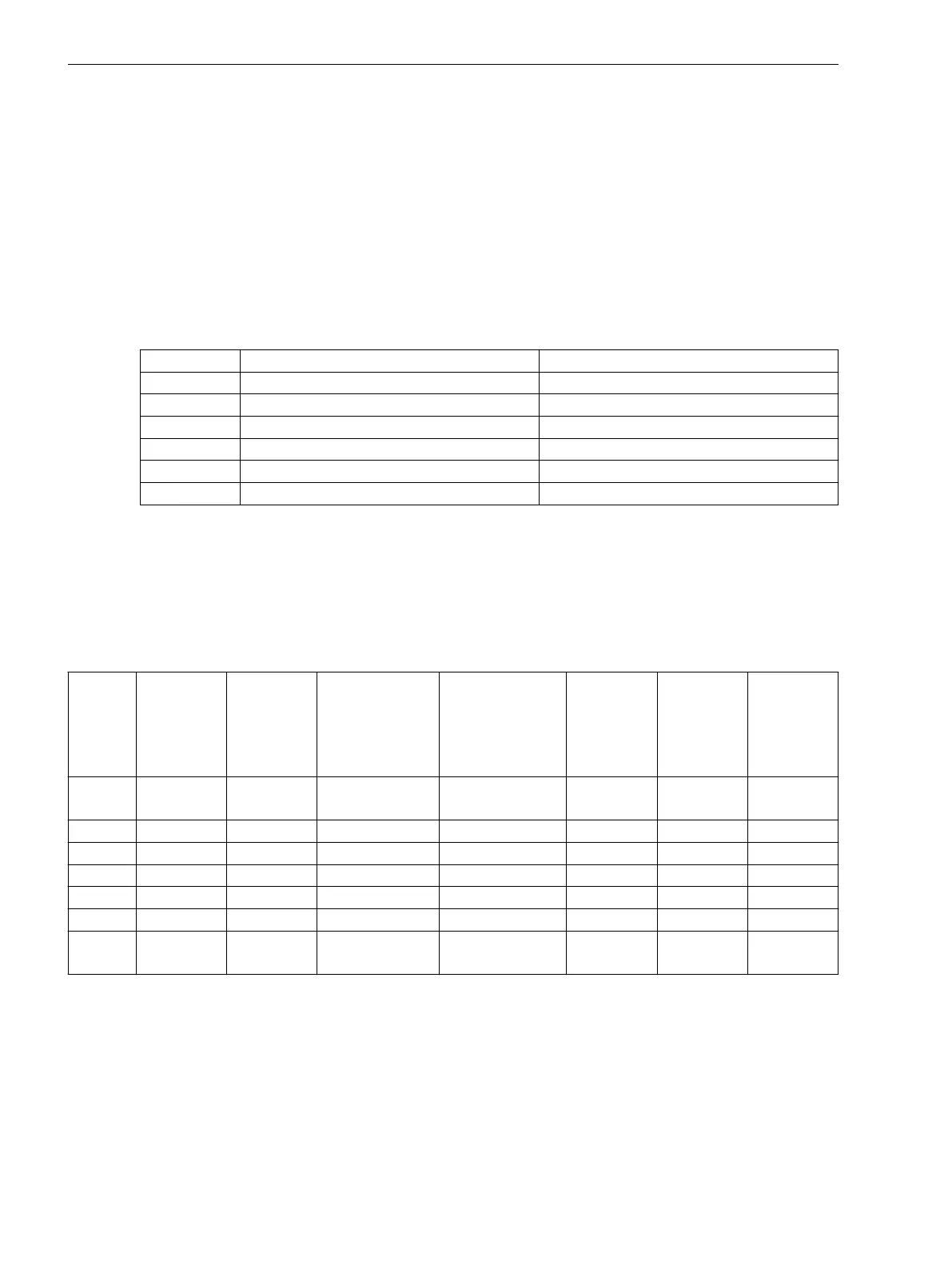
For the voltages U1, U2 and the difference voltage, the following secondary sides values apply and they can
be as well displayed as operational measured values:
BCD
code at
the
operator
panel
Display at
the device
U
OS Trans
/kV
Primary
U
OS Trans
/V
als
“secondary”
transformer
value
Ud; Ue/V
Secondary
(generator side)
U2/V
Secondary
(corrected)
U1/V
Secondary
dU/V
Secondary
0000 ****
(invalid)
--- ---
0001 –2 498.75 95.00 100.0 95.0 100.0 –5.0
0010 –1 511.875 97.50 100.0 97.5 100.0 –2.5
0011 0 525.000 100.00 100.0 100.0 100.0 0
0100 1 538.125 102.50 100.0 102.5 100.0 +2.5
0101 2 551.250 105.00 100.0 105.0 100.0 +5.0
0110 ****
(invalid)
--- ---
GOOSE Application
It is possible to transfer a transformer tap setting per GOOSE via the Ethernet from a SIPROTEC device (e.g.
6MD66x) to the device 7VE632x for evaluation in the synchronization function. For this purpose, the trans-
former tap message in the transmitter must be configured to the target system interface. In receiver 7VE632x
an external metered value is required from the information catalog for detection of the external transformer
tap. This metered value must be configured to source system interface. The "link" between transmitter and
receiver is effected in the station configuration (see Manual “Ethernet & IEC 61850, Start Up”).
The external metered value can now be selected in the synchronization function in the transformer-tap tab.
The settings for the transformer taps must be set as set out above.
Functions
2.2 Paralleling Functions
72 SIPROTEC 4, 7VE61 and 7VE63, Manual
C53000-G1176-C163-3, Edition 10.2017

 Loading...


