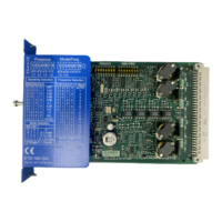
Internal circuit diagram
Figure 5-20 DP interface internal circuit diagram
Terminal designations of the DP interface module
Terminal Meaning Explanation
L+ Power supply 24 V DC
M Ground Ground to 24 V DC
FE Functional ground Shielding, equipotential bonding
Interfaces of the DP interface module
Interface Meaning Explanation
X1 Device interface Connection of PC / PG, diagnostics display
X2 System interface Safety relay connection
PROFIBUS DP 9-pin sub D socket Connection to PROFIBUS DP
Operating elements of the DP interface
Element Meaning Explanation
SET Operating the display See Chapter "Operating the 3RK35 DP interface
(Page 197)".
MODE Operating the display
Display elements of the DP interface module
Element Meaning
DEVICE Status
BF Bus error
SF Group error
Description of the hardware
5.1 Description of the individual modules
SIRIUS 3RK3 Modular Safety System
Equipment Manual, 07/2020, NEB926253002000/RS-AC/006 119

 Loading...


