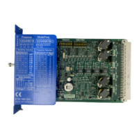
These AS‑i output slaves are each assigned an AS‑i address to which the safety-related AS‑i
output being set or reset responds.
Note
Exchange of safety-related signals
If safety-related AS-i input slaves are simulated simultaneously, the number of simulated safety-
related AS-i output slaves for controlling safety-related AS-i outputs is reduced accordingly.
Safety-related AS-i outputs can be set or reset using the "AS‑i1..4F‑DO" output function and
"Output cell" cell function.
Up to four fail-safe signals can be transmitted for each AS‑i address using output functions
"AS‑i1..4F‑DO." At any one time, only one of these fail-safe signals may be active.
If the output is set and reset using the "Output cell" cell function, only the rst of the four fail-safe
signals can be used.
7 x 4 bit code sequences of the safety-related AS‑i output slaves
These slaves send 7 x 4 bit code sequences, which are permanently assigned for each address,
on the address congured for this. The safety-related AS‑i outputs to be set and reset behave like
safety monitors and monitor the address assigned to them on the AS‑i bus.
Non-safety-related auxiliary control signals (AUX1/AUX2)
In addition to the safety-related control signals (code sequences) of the AS‑i outputs, non-safety-
related auxiliary control signals (AUX1, AUX2) can also be transmitted. These are used, for
example, to acknowledge a restart inhibit or to release errors at AS‑i outputs. Additional
information can be found in the relevant documentation of the safety-related AS-i output.
The auxiliary control signals AUX1 and AUX2 are dened as pulses. That is why these terminals
must not be used for static signals. This pulse is generated as soon as an edge change from zero
to one is detected at the respective AUX input (an edge change from one to zero is not taken into
consideration).
If a simultaneous edge change is detected for both inputs, the pulse for AUX2 is output after the
pulse for AUX1.
Interconnection in the logic diagram
The AS‑i outputs are set or reset in the interconnection logic either by means of an "output cell"
(Q1 only) or by means of the function element "AS‑i 1..4F‑DO."
Operation
6.5 Connecting to the AS-i master via AS-Interface
SIRIUS 3RK3 Modular Safety System
Equipment Manual, 07/2020, NEB926253002000/RS-AC/006 221

 Loading...


